Modbus® Server User Guide
Trademark Notices Comtrol, DeviceMaster, and PortVision are registered trademarks of Comtrol Corporation. Ethernet is a registered trademark of Digital Equipment Corporation, Intel, and Xerox Corporation. Modbus is a registered trademark of Schneider Electric. PLC is a registered trademark of Allen-Bradley Company, Inc. Other product names mentioned herein may be trademarks and/or registered trademarks of their respective owners. Third Edition, June 2, 2014 Copyright © 2010 - 2014. Comtrol Corporation.
Table of Contents Modbus Server Application Overview ..............................................................................5 Recommended Chassis ................................................................................................................................. 5 Terms and Definitions .................................................................................................................................. 6 What is Modbus? .......................................................
Table of Contents iv - Table of Contents DeviceMaster UP Modbus Server User Guide: 2000535 Rev.
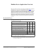
Modbus Server Application Overview This section defines the software functionality for the Modbus Server application and provides an overview of other Comtrol Modbus solutions (Page 9). The Modbus Server application was designed to provide enhanced connectivity for OPC servers and applications that require Modbus/RTU communications. While standard gateways provide connectivity for only one application per serial port, Modbus Server provides connectivity for up to six applications per serial port.
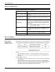
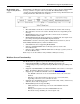
Terms and Definitions Terms and Definitions This table provides Modbus Server definitions. Term Definition The method of operation when a DeviceMaster or an Master (or Client) Mode application is operating as a Master or the message originator. Slave (or Server) Modbus/RTU The method of operation when a DeviceMaster or an application is operating as a Slave or the message receiver.
Modbus/TCP (Not supported by Modbus Server) Modbus/TCP (Not supported by Modbus Server) Modbus/TCP is an Ethernet network based protocol that contains a Modbus/RTU message, with the exception of the 2 byte CRC. The Modbus/TCP message contains a header with information designed to provide message identification and routing information. The format is as follows: Where: • The terms Master or Client are used to identify the sender of the message.
Modbus Server Functionality • • • System monitoring to ensure gateway operation: - Gateway busy. - Application message time-outs. Advanced diagnostics web pages: - Modbus/RTU device specific statistics and status. Up to 255 Modbus/RTU devices per port can be monitored simultaneously. - Serial port specific statistics, response timing, and status. - Serial port message logging.
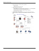
Other Comtrol Modbus Solutions Other Comtrol Modbus Solutions Comtrol provides several other Modbus solutions other than Modbus Server that include: Modbus Router • Modbus Router • Modbus/TCP Modbus Router firmware was developed to provide innovative network-wide Modbus connectivity from a wide variety of Modbus masters to a wide variety of local and remote Modbus slaves.
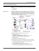
Modbus/TCP - Multiple Modbus Master and Slave Types, Serial and Ethernet Raw/ASCII Devices Modbus/TCP Multiple Modbus Master and Slave Types, Serial and Ethernet Raw/ASCII Devices • Master-to-Master connectivity (via Shared Memory subsystem) • Isolation of serial Modbus slaves (via Private Serial Bus connectivity) • Write protection of serial Modbus slaves • Modbus Device ID conflict resolution The Modbus/TCP firmware has been designed to provide great flexibility for connecting both Modbus serial
Installation Overview Use this section to locate software and installation documentation for the DeviceMaster UP to quickly install and configure Modbus Server. An installation follows these basic steps. 1. Connect the DeviceMaster UP to the network. If necessary, use the appropriate hardware installation document for your DeviceMaster UP. 2. Install PortVision DX. You can refer to the PortVision DX Overview subsection to locate PortVision DX and install it easily.
Installation Overview • Use PortVision DX to monitor any DeviceMaster on the network. The DeviceMaster does not have to be on the same local network segment as PortVision DX for monitoring purposes. Installing PortVision DX PortVision DX requires that you connect the DeviceMaster UP to the same network segment as the Windows system during the configuration process. 1. If necessary, download the latest version of PortVision DX from ftp://ftp.comtrol.com/dev_mstr/portvision_dx/. 2.
Installing PortVision DX 5. Click Next or optionally, browse to a different location and then click Next. 6. Click Next to configure the shortcuts. 7. Click Install. DeviceMaster UP Modbus Server User Guide: 2000535 Rev.
Installation Overview 8. Depending on the operating system, you may need to click Yes to the Do you want to allow the following program to install software on this computer? query. 9. Click Launch and Finish in the last installation screen. 10. Click the Scan button in the Toolbar so that PortVision DX locates the DeviceMaster UP.
Configuring the Network Settings 11. Select the products for which you want to scan. If you do not have any RocketLinx managed switches or IO-Link Masters it saves scanning time if you do not scan for them.. Note: If the Comtrol Ethernet-attached product is not on the local segment and it has been programmed with an IP address, it will be necessary to manually add the Comtrol Ethernet-attached product to PortVision DX. 12.
Installation Overview 5. Highlight the DeviceMaster for which you want to program network information and open the Properties screen using one of these methods. • Double-click the DeviceMaster in the Device Tree or Device List pane. • Highlight the DeviceMaster in the Device Tree or Device List pane and click the Properties button.
Configuring the Network Settings 6. Optionally, rename the DeviceMaster UP in the Device Name field. Note: The MAC address and Device Status fields are automatically populated and you cannot change those values. 7. Optionally, enter the serial number, which is on a label on the DeviceMaster. 8. If necessary, you can change the Detection Type. • REMOTE means that the DeviceMaster is not connected to this segment of the network and it uses IP communications, not MAC communications.
Installation Overview Uploading Modbus Server Use this section to upload Modbus Server on the DeviceMaster UP using PortVision DX. 1. Make sure that you download the latest Modbus Server version. 2. Execute the .msi to unpackage the Modbus Server firmware file. 3. If necessary, open PortVision DX > Start/Programs > Comtrol > PortVision DX > PortVision DX or use the desktop shortcut. 4.
Installing the Serial Port Redirector (Optional) It may take a few moments for the firmware to upload onto the device. The device will reboot itself during the upload process. 6. Click Ok to the advisory message about waiting to use the device until the status reads ON-LINE. In the next polling cycle, PortVision DX updates the List View pane and displays the new Modbus Server version.
Installation Overview 5. Click Next to the Configure Shortcuts screen. 6. Click Install. 7. Click Finish. 20 - Installation Overview DeviceMaster UP Modbus Server User Guide: 2000535 Rev.
Configuring Port Redirector COM Ports Configuring Port Redirector COM Ports Use the following procedures to: • Add a DeviceMaster UP port • Configure the port for the secure port redirector If necessary, refer to the secure port redirector help system for more information. Adding a Secure Port Use the following procedure to add a secure port or ports.
Installation Overview Configuring the Secure COM Port Use the following procedure to configure the port. 1. Double-click the port that you want to configure. 2. Optionally click the Connection Settings tab, click Auto-reconnect when connection is broken, set the Reconnect interval, set Cache data when the connection is broken, and then Ok. 3. Click the SSL Security tab and then click Use SSL for connection to remote side.
Configuring the Secure COM Port 4. Click the Settings tab and select the appropriate serial port settings. 5. Optionally, click the Extra Strings tab and enter the appropriate values. 6. Click OK to save the settings for the DeviceMaster UP. 7. Repeat the above procedure for each port that you want to use as a secure COM port. 8. Close the Secure Port Redirector window when you are done. You are now ready to connect the serial devices to the DeviceMaster UP ports.
Installation Overview 24 - Installation Overview DeviceMaster UP Modbus Server User Guide: 2000535 Rev.
Embedded Web Pages All configuration and status information is provided through embedded web pages for Modbus Server. Note: The latest Modbus Server firmware must be installed before you can configure network or serial/socket port characteristics. For firmware installation and setup information, see Installation Overview on Page 11 or the PortVision DX help system.
Server Configuration (Main) Page Server Configuration (Main) Page Access the main DeviceMaster web page (Server Configuration) from PortVision DX or enter the IP address of the DeviceMaster in the Address box of your web browser. The Server Configuration page displays the software version and current network configuration for the DeviceMaster. In addition, the Server Configuration page links to the configuration, statistics, and diagnostics pages, which are discussed in the table below.
Serial Interface Configuration Page Serial Interface Configuration Page The Serial Interface Configuration page provides: • Links to the following pages: - Server Configuration (Main) Page (Page 26) - Serial Interface Communications Statistics Page (Page 34) - Serial Interface Logs Page (Page 36) - Known Modbus/ RTU Device List Web Page (Page 33) for all ports or a specific port. Clicking the Display Devices (all) link or the Display Devices for a specific port.
Edit Port Configuration Page the Edit Port Configuration page. Select the appropriate serial port number to configure the serial port characteristics. Edit Port Configuration Page Use the Edit Port Configuration page to change a serial port’s configuration parameters. To access the Edit Port Configuration page, select the appropriate port number link (for example, Port 1) on the Serial Interface Configuration page.
Edit Port Configuration Page Name Value(s) Description Serial Configuration All models, except 2-port models: Mode Baud Rate • RS-232 (default) • RS-422 • RS-485 2-port models: • RS-232 (default) • RS-422 • RS-485_2-wire • RS-485 4-wire Master • RS-485 4-wire Slave Selectable serial mode of communications. 300, 600, 1200, 2400, 4800, 9600, 19200, 38400 Selectable serial port baud rates. (default), 57600, 115200, 230400 None (default) Parity Even Selectable parity values.
Edit Port Configuration Page Name Discard Rx Packets With Errors Duplicate Modbus/ RTU Protocol for All Ports. Value(s) Description If selected, the DeviceMaster will drop all packets received with parity, framing, or overrun errors. On/Off (Default = On) Note: Modbus/RTU messages with invalid CRCs will always be discarded independent of this setting. If selected, will apply the Modbus/RTU protocol settings to all serial ports.
Edit Network Configuration Page Edit Network Configuration Page You can use the Edit Network Configuration page to change the DeviceMaster network configuration after using PortVision DX for initial network configuration. Use the following procedure to change the network configuration. 1. Select the IP configuration type (Use DHCP or Use Static configuration below:). 2. If you select Use Static configuration below, enter a valid IP address, subnet mask, and IP gateway for your network.
Edit Network Configuration Page 32 - Embedded Web Pages DeviceMaster Modbus Server User Guide: 2000535 Rev.
Embedded Diagnostic and Statistics Pages This section discusses embedded diagnostic and statistics web pages for Modbus Server. Known Modbus/RTU Device List Web Page The Known Modbus/RTU Device List page provides device specific status and statistics for each device on one or all ports. Know Modbus/RTU Device List Page Device ID Unit identifier associated with this device. Status of device: Active? • Yes means that the last request received a valid response and did not time out.
Serial Interface Communications Statistics Page Serial Interface Communications Statistics Page Where the following definitions apply:. Counter Name Description TX Byte Count (To Device) Number of bytes transmitted out the serial port. TX Message Count Number of messages transmitted out the serial port. RX Byte Count (From Device) Number of bytes received on the serial port. RX Response Count Number of responses received on the serial port.
Serial Interface Communications Statistics Page Counter Name Description Parity Error Count Number of parity errors received on the serial port. Typically occurs due to an incorrect parity setting. Framing Error Count Number of framing errors received on the serial port. Typically occurs due to an incorrect baud rate or stop bit setting. Overrun Error Count Number of overrun errors received on the serial port..
Serial Interface Logs Page Counter Name Description Dropped RX Messages Due to Invalid CRCs Number of messages from the application(s) that were dropped due to an invalid Modbus/RTU CRC. TX Byte Count (To Device) Number of bytes transmitted out the serial port. Serial Interface Logs Page The following page displays the serial message transmitted and received during normal operation. The format is as follows: Pkt(N): ddd:hh:mm:ss.
Troubleshooting and Technical Support This section contains troubleshooting information for your DeviceMaster. You should review the following subsections before calling Technical Support because they will request that you perform many of the procedures or verifications before they will be able to help you diagnose a problem.
General Troubleshooting • If the device has a power switch, turn the device’s power switch off and on, while watching the LED diagnostics. • If the DeviceMaster does not have a power switch, disconnect and reconnect the power cord. • Verify that the network IP address, subnet mask, and gateway is correct and appropriate for the network. If IP addressing is being used, the system should be able to ping the DeviceMaster.
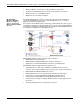
Daisy-Chaining DeviceMaster 2E/4-Port Units Daisy-Chaining DeviceMaster 2E/4-Port Units The DeviceMaster 2E/4-port models with external power supplies follow the IEEE specifications for standard Ethernet topologies. When using the UP and DOWN ports, the DeviceMaster 2E/4 is classified as a switch. When using the UP port only, it is a simple end node device.
Technical Support Technical Support It contains troubleshooting procedures that you should perform before contacting Technical Support since they will request that you perform, some or all of the procedures before they will be able to help you diagnose your problem. If you need technical support, use one of the following methods. Comtrol Contact Information Downloads ftp://ftp.comtrol.com/html/up_modbus_server_main.htm Web site http://www.comtrol.com Phone 763.957.