RocketPort and RocketModem Series Driver Installation Windows 2000 Operating System
Trademark Notices Comtrol, RocketModem, and RocketPort are trademarks of Comtrol Corporation. Microsoft and Windows are registered trademarks of Microsoft Corporation. Other product names mentioned herein may be trademarks and/or registered trademarks of their respective owners. Third Edition, January 14, 2003 Copyright © 2000 - 2003. Comtrol Corporation. All Rights Reserved.
Table of Contents Table of Contents Table of Contents ................................................................................................................................. 3 Overview ................................................................................................................................................ 5 How to Use this Document ..........................................................................................................................
Table of Contents Table of Contents 4
Overview The following subsection gives you information that you need to prepare your system for installing a RocketPort adapter. How to Use this Document You can use the interactive Table of Contents to locate the information you need. Driver Requirements This document discusses installing and configuring the RocketPort and RocketModem device driver for the Windows 2000 operating system. The RocketPort or RocketModem requires at least one host system running Windows® 2000.
Upgrading Your Operating System to Win2000 Upgrading Your Operating System to Win2000 If you are upgrading from another operating system, follow these steps: Note: Do not use the Update Driver feature in the Device Manager to upgrade the driver. 1. Before upgrading the operating system, remove the driver from the Windows 95/98 or Windows NT operating system. See the Removing or Disabling the Adapter discussion. 2. Turn off the system, remove the boards, and set them aside. 3.
Driver and Adapter Information The following subsections discuss driver and adapter installation and removal. It also discusses adapter and port configuration. If you have installation problems, see the troubleshooting subsection. Removing or Disabling the Adapter Adapters cannot be removed through the Main Setup window. Use the following procedure to remove adapters: 1. On the Windows desktop, right-click on the My Computer icon and select Manage. 2. Double-click on the Device Manager. 3.
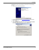
PCI Adapters If the operating system finds the adapter but not the driver, use the following procedure: 1. The Found New Hardware Wizard starts. 2. If you have not copied the most recent version of the driver on to the hard drive, do it now. 3. Select the Next button 4. Select the Display a list of the known drivers for this device so that I can choose a specific driver option. Select the Next button.
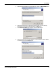
PCI Adapters 5. Select the desired adapter from the Models list. Select the Have Disk button. 6. Select the Browse button to display the Open window. Go to the directory where the driver files are located and select the OK button. 7. The Install from Disk page reappears. Select the OK button. 8. The Select a Device Driver page reappears. Confirm that the desired adapter is selected, and select the Next button.
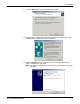
PCI Adapters 9. Select the Next button to start the installation process. 10. If the procedure displays the Digital Signature Not Found dialog box, select the Yes button to complete the driver installation. 11. Select the Finish button.The new driver is now installed and the system starts to configure the COM Ports. Note: You may have to shut down and restart your system before the changes take effect.
ISA Adapters ISA Adapters Before installing the driver, you should install the hardware and restart the system. To install the driver, use the Add/Remove Hardware wizard. Note: This driver only supports one ISA adapter. If installing an ISA board, you must set the I/O DIP switch and you may need to change the software setting. See Setting I/O Addresses and DIP Switches (ISA Only), if necessary. 1. On the Windows desktop, right-click the My Computer icon. 2. Select the Properties button. 3.
Setting I/O Addresses and DIP Switches (ISA Only) Setting I/O Addresses and DIP Switches (ISA Only) Software I/O Address This discussion concerns ISA adapters only. This driver supports only one ISA adapter. When you install an ISA adapter, you must set the base I/O address in two places • In the driver software • On the adapter itself, using a block of DIP switches. During installation, the software base I/O address is set to default values by the Add/Remove Hardware Wizard.
Upgrading the Driver Upgrading the Driver Use this procedure if you want to upgrade the driver in the Windows 2000 operating system. Use the following procedure to install a new driver: 1. Unzip the file into a new subdirectory, for example: \Comtrol. 2. On the Windows desktop, right-click on the My Computer icon and select Manage. 3. Select the Device Manager. 4. Open the Multi-port serial adapters item. 5.
Upgrading the Driver 9. Select the Next button to start the Upgrade Driver Wizard. 10. Select the Display a list of the known drivers for this device so that I can choose a specific driver option and the Next button.
Upgrading the Driver 11. Select the Have Disk button. 12. Browse to the location of the driver file that you extracted, and then select the Open button. 13. Select the OK button. 14. Highlight the device and select the Next button.
Upgrading the Driver 15. Select the Next button. 16. Select Yes at the Digital Signature Not Found dialog box. 17. Select the Finish button to complete the driver installation process.
Accessing the Main Setup Tab 18. Select the Close button when you return to the Properties window. 19. Select Yes to restart your system. 20. After you restart the computer, return to the Device Manager, and select the Enable option for the adapter. After you complete the driver installation, additional steps may be necessary to configure the ports using the Main Setup tab. Accessing the Main Setup Tab 1. On the Windows desktop, right-click the My Computer icon and select Manage from the short-cut menu.
Changing Device Properties Changing Device Properties You can change the following device properties: • Device name • Starting COM port number. In addition, you can configure primary and back up systems and establish a time out period. To change device properties, follow this procedure to access the Device Setup tab: 1. Access the Main Setup tab. 2. Highlight the device name and select the Properties button. 3. After making your changes, select the OK button and follow any other driver prompts.
Configuring Device Properties Configuring Device Properties You can optionally configure the following Device Properties: • Verbose event log for diagnostic purposes. • Scan rate to adjust latency for timing-critical applications. • Enable RS-485 mode. To set the previous options, use the following procedure: 1. Access the Main Setup tab. 2. Select the Options tab. 3. Enable the features you want to use. 4.
Configuring Port Properties Configuring Port Properties You can also configure specific port properties for this adapter: • Override and lock baud rate to ... • Timeout on transmit data on port close • Map CD to DSR • Map 2 stop bits to 1 • Wait on physical transmission before completing write • Emulate modem hardware RING signal • Clone all Comtrol ports for this system Use the following procedure to access the Port Properties tab: 1. Access the Main Setup tab. 2.
Configuring Modems Overview After installing the hardware and driver for Windows 2000, you can use this discussion to configure modem COM ports. Installing Modems The following instructions were developed using Comtrol modem products. If you are using another brand of modem, note that some prompts and screen descriptions may differ from those shown. Follow these steps: 1. Connect the modem to the desired port. 2. Turn on the modem. 3.
Installing Modems 4. Select the Don’t detect my modem; I will select it from a list check box, and select the Next button. Note: While Windows 2000 can automatically detect modems, we advise against using this option as auto-detect feature may cause some multiprocessor systems to lock up. 5. Select the appropriate manufacturer and model, and select the OK button.
Installing Modems 6. Select the port you to which you want to install the modem. Select the Next button 7. Select the Finish button. The modem software is installed on the selected ports. Note: For help configuring modem properties, see the Windows Help system.
Installing Modems 8. If you need to configure dialing properties (country, area code, calling card number, and so on), select the Dialing Rules tab, make the needed changes, then select the OK button. 9. When the Phone and Modem Options window reappears, select the Close button.
Comtrol Tools This section discusses the following utilities that are installed with most Comtrol drivers for Microsoft operating systems: • Test Terminal program (wcom32.exe), which can be used to troubleshoot communications on a port-by-port basis (Using Test Terminal on Page 27). • Port Monitor program (portmon.exe), which checks for errors, modem control, and status signals (Using Port Monitor on Page 30). In addition, it provides you with raw byte input and output counts.
Installing the Utilities (Windows 2000 and Windows XP) 3. Select the Next button to install the Utilities in the default subdirectory. 4. Select the Next button to begin the installation. 5. Select the Finish button to complete the Utilities installation.
Using Test Terminal Using Test Terminal WCOM32 is a terminal program that enables you to open a port, send characters and commands to the port, and toggle the control signals. Note: WCOM32 will not work on ports used by RAS if Remote Access Service is running or any other application is using the port. If you are using RAS, you must stop the service before starting WCOM32 to test RAS COM ports. To test ports that are not used by RAS, you do not need to stop RAS. Follow these steps: 1.
Testing a Comtrol Device If the COM port is available, a terminal window appears: Note: Notice the button in the terminal window. If this option is activated, it is green and uppercase ( ), the COM port internal loopback feature is activated, and the data is returned by the COM port hardware. If this option is deactivated, it is gray and lowercase ( ), the internal loopback is deactivated, and the data is sent out of the COM port.
Testing a Comtrol Device (RS-485) Testing a Comtrol Device (RS-485) Perform the following procedure to determine if a port or ports are functioning properly. 1. Connect a straight-through cable from Port 1 to Port 2. Note: See the hardware installation document for the Comtrol device if you need to build a cable. If testing ports other than Ports 1 and 2, simply connect the cable between any two ports. 2. Open a session for each port. 3. Enter data into the Port 1 session.
Using Port Monitor Using Port Monitor The Port Monitor program (portmon.exe) offers a summary of all Comtrol device statistics in one spreadsheet view. It also enables you to verify operation of all Comtrol device ports from a single window. The Port Monitor display follows the familiar spreadsheet model: each COM port is a horizontal row, and each vertical column displays a variable or value for the respective COM port. For definitions of the abbreviations used, see Port Monitor Variables on Page 33.
Changing Screen Appearance Once the monitor window appears, Port Monitor is active and collecting data. If any cumulative data has been saved from previous sessions, it is automatically brought in and used. Port Monitor continues to run and collect data until you terminate it, at which point all accumulated data is automatically saved for use in the next session. Changing Screen Appearance While Port Monitor is running, there are a number of commands and controls that change the appearance of the screen.
Report Configuration Report Configuration • Use Color0 to set the column character color when the value is zero. • Use Color1 to set the column character color when the value is not zero. • When done, click OK to save your changes and return to Port Monitor. To configure reports, select Config from the Edit menu. The Single report options cover all ports and are overwritten each time the reports are generated.
Port Monitor Files Port Monitor Files Port Monitor creates and uses the following files: • portmon.vew • calcs.dat The default column layout is saved in portmon.vew. If you have been experimenting with the appearance of the monitor screen, you can use the File menu Save option to save your customized layout in another .vew file. You can retrieve this file later by selecting the Open option from the File menu, or you can select the View Default option from the Edit menu to retrieve portmon.
Port Monitor Variables Variable Description RxMinCPS Last minute average of receive characters per second. TxCPSMinAvMax Peak TxCPSInst for the last minute. RxCPSMinAvMax Peak RxCPSInst for the last minute. TxCPSHourAvMax Peak TxMinCPS for the last hour. RxCPSHourAvMax Peak RxMinCPS for the last hour. TxCPSDayAvMax Peak TxMinCPS for the last day. RxCPSDayAvMax Peak RxMinCPS for the last day. TxTotalRaw Total number of transmit bytes raw data from the device driver.
Using Peer Tracer Variable Description TxPkts Raw count of total transmit packets sent. RxPkts Raw count of total receive packets sent. OverrunErrors Total count of receive overrun errors. FramingErrors Total count of receive framing errors. ParityErrors Total count of receive parity errors. OverrunErrorsRaw Total count of receive overrun errors, from the device driver. FramingErrorsRaw Total count of receive framing errors, from the device driver.
Log Functions Log Functions All logging functions are found under the File menu. To start keeping a log, select Log to Disk from the File menu. The other options on this menu are View Disk Log, Clear Disk Log, Clear Screen, and Exit. Using Peer To use peer, simply type in commands at the : prompt. (It may be necessary to press Enter to make the : prompt appear.) For example, to examine COM5, type: PORT COM5 To gather some information about the port, type: STAT .
Troubleshooting and Technical Support This section contains troubleshooting information for your Comtrol device. You should review the following subsections before calling Technical Support because they will request that you perform many of the procedures or verifications before they will be able to help you diagnose the problem. Troubleshooting If you are having trouble with a RocketPort or RocketModem, try the following.
Technical Support Technical Support If you need technical support, contact Comtrol using one of the following methods. Contact Method Corporate Headquarters Comtrol Europe FAQ/Online http://support.comtrol.com/support.asp Downloads http://support.comtrol.com/download.asp Email support@comtrol.com support@comtrol.co.uk Web site http://www.comtrol.com http://www.comtrol.co.
Index A Add Hardware Wizard 21 C changing device properties 18 Comtrol contact information 38 configuring device properties 19 port properties 20 D dialing properties 24 dialing rules 24 dialing rules tab 24 disabling an adapter 7 E email support 38 F FAQ/Online 38 fax contact information 38 Found New Hardware Wizard 8 H hardware installation 5 I input counts 30 installing the driver 7 installing modems 21 installing the utilities 25 L loopback test 28 M Main Setup Tab 17 O online support 38 output counts 3