Hardware User Guide
Trademark Notices Comtrol, DeviceMaster, and PortVision are registered trademarks of Comtrol Corporation. Ethernet is a registered trademark of Digital Equipment Corporation, Intel, and Xerox Corporation. Microsoft and Windows are registered trademarks of Microsoft Corporation in the United States and/or other countries. Modbus is a registered trademark of Schneider Electric. PLC is a registered trademark of Allen-Bradley Company, Inc. RedBoot is a trademark of Red Hat, Inc.
Table of Contents Getting Started .......................................................................................................................5 Quick Start ...................................................................................................................................................... 5 Locating Software and Documentation ................................................................................................... 6 Hardware Installation...............................
Table of Contents RedBoot Procedures............................................................................................................41 Accessing RedBoot Overview ................................................................................................................... 41 Establishing a Serial Connection ............................................................................................................ 42 Establishing a Telnet Connection.........................................
Getting Started This guide discusses initial DeviceMaster UP installation and hardware configuration for the DeviceMaster UP with 16-ports. This guide does not discuss configuring the port characteristics or protocol-specific programming information. See Locating Software and Documentation on Page 6 to locate the firmware and the appropriate documentation for your environment.
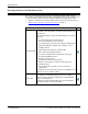
Getting Started Locating Software and Documentation You can access the appropriate firmware assembly, PortVision DX, and the DeviceMaster UP documentation from the CD shipped with the DeviceMaster UP or you can download the latest files using the links in the appropriate table: • Software and firmware, which is independent of the protocol loaded (below) • Modbus Router Firmware and Documentation on Page 7 DeviceMaster UP Software and Firmware FTP PortVision DX is the application for Windows that you
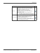
Getting Started Modbus Router Firmware and Documentation FTP Modbus Router (.msi) contains the firmware and supporting files. The firmware provides embedded configuration web pages. You may need to update the DeviceMaster UP with the latest version. Firmware Depending on the model you purchased, the DeviceMaster UP may or may not have the Modbus Router firmware loaded.
Getting Started 8 - Getting Started DeviceMaster UP 16-Port Hardware User Guide: 2000596 Rev.
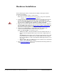
Hardware Installation Use the following procedure to install the DeviceMaster UP 16-port with an external power supply. 1. Place the DeviceMaster UP on a stable surface. Note: Do not connect multiple units until you have changed the default IP address, see Initial Configuration on Page 35. 2. Connect the DeviceMaster UP to the same Ethernet network segment as the host PC using either port labeled 10/100 using a standard Ethernet cable.
Hardware Installation 10 - Hardware Installation DeviceMaster UP 16-Port Hardware User Guide: 2000596 Rev.
Configuring the DeviceMaster UP The DeviceMaster UP platform includes PortVision DX, which is the management application that you use to manage all Comtrol Ethernet-attached devices. Note: Existing installations: PortVision DX replaces PortVision Plus, you must install PortVision DX v3.02 or higher to upload the latest firmware.
Configuring the DeviceMaster UP PortVision DX Requirements Use PortVision DX to identify, configure, update, and manage the DeviceMaster UP on the following Windows operating systems: • Windows 8/8.
Configuring the DeviceMaster UP 3. Click Next on the Welcome screen. 4. Click I accept the terms in the License Agreement and Next. 5. Click Next or optionally, browse to a different location and then click Next. DeviceMaster UP 16-Port Hardware User Guide: 2000596 Rev.
Configuring the DeviceMaster UP 6. Click Next to configure the shortcuts. 7. Click Install. 8. Depending on the operating system, you may need to click Yes to the Do you want to allow the following program to install software on this computer? query. 14 - Configuring the DeviceMaster UP DeviceMaster UP 16-Port Hardware User Guide: 2000596 Rev.
Configuring the DeviceMaster UP 9. Click Launch PortVision DX and Finish in the last installation screen. 10. Depending on the operating system, you may need to click Yes to the Do you want to allow the following program to make changes to this computer? query. 11. Select the Comtrol Ethernet-attached products that you want to locate and then click Scan.
Configuring the DeviceMaster UP Configuring the Network Settings Use the following procedure to change the default network settings on the DeviceMaster UP for your network. Default Network Settings IP address: 192.168.250.250 Subnet mask: 255.255.0.0 Gateway address: 192.168.250.1 Note: Technical Support advises configuring one new DeviceMaster UP at a time to avoid device driver configuration problems.
Configuring the DeviceMaster UP 5. Highlight the DeviceMaster UP for which you want to program network information and open the Properties screen using one of these methods. • Double-click the DeviceMaster UP in the Device Tree or Device List pane. • Right-click the DeviceMaster UP in the Device Tree or Device List pane and click Properties in the popup menu • Highlight the DeviceMaster UP in the Device Tree or Device List pane and click the Properties button.
Configuring the DeviceMaster UP 6. Optionally, rename the DeviceMaster UP in the Device Name field. Note: The MAC address Device Status fields are automatically populated and you cannot change those values. 7. Optionally, enter the serial number, which is on a label on the DeviceMaster UP. 8. If necessary, you can change the Detection Type. • REMOTE means that the DeviceMaster UP is not connected to this segment of the network and it uses IP communications, not MAC communications.
Configuring the DeviceMaster UP 11. Click Close to exit the Properties window. 12. If if applicable, check your firmware version to make sure that it is the latest version using the next subsection, Checking the Protocol Firmware Version. 13. If necessary, use Uploading Protocol-Specific Firmware on the DeviceMaster UP on Page 20 to update or load the firmware for your DeviceMaster UP. Checking the Protocol Firmware Version Use PortVision DX to check the firmware version before configuring the ports.
Configuring the DeviceMaster UP Uploading Protocol-Specific Firmware on the DeviceMaster UP Some DeviceMaster UP models come from the factory with SocketServer firmware, which provides an interface to TCP/IP socket mode configuration and services, installed on the device. If your DeviceMaster UP contains SocketServer, you must replace SocketServer with Modbus Router. The CD shipped with the DeviceMaster UP contains the required firmware and support files in a self-installing (.
Configuring the DeviceMaster UP 4. Click Yes to upload the firmware. 5. Click OK to the advisory message about waiting until the DeviceMaster UP is on-line and in the next minute the DeviceMaster UP unit or units should display ON-LINE in the Status field. 6. Go to the DeviceMaster UP Modbus Router User Guide for information about configuring the serial port or ports using the web page and programming your PLCs.
Configuring the DeviceMaster UP Customizing PortVision DX You can customize how PortVision DX displays the devices. You can even create sessions tailored for specific audiences. You can also add shortcuts to other applications using Tools > Applications > Customize feature. The following illustrates how you can customize your view. See the PortVision DX Help system for detailed information about modifying the view. For example, the above screen shot illustrates devices layered in folders.
Configuring the DeviceMaster UP Accessing DeviceMaster UP Documentation from PortVision DX You can use this procedure in PortVision DX to download and open the previously downloaded documents for the DeviceMaster UP. You can also check to see if you have the latest version of the documentation using PortVision DX. How to Download Documentation Use this procedure to initially download a document or documents. 1.
Configuring the DeviceMaster UP How to Open Previously Downloaded Documents Use the following procedure to access previously downloaded documents in PortVision DX. Note: Optionally, you can browse to the Program Files (x86) > Comtrol > PortVision DX > Docs subdirectory and open the document. 1. If necessary, open PortVision DX > Start/Programs > Comtrol > PortVision DX > PortVision DX or use the desktop shortcut. 2. Click Help > Documentation. 3.
Connecting Serial Devices Note: If you have a DeviceMaster UP with 1, 2, or 4-ports, use the DeviceMaster UP Hardware Installation and Configuration Guide because the RJ45 connectors have different pin outs. This section discusses connecting your serial devices to the DeviceMaster UP. It also provides you with information to build serial cables and loopback connectors to test the serial ports. Use the appropriate subsection to connect asynchronous serial devices to the DeviceMaster UP ports.
RJ45 Null-Modem Cables (RS-232) RJ45 Null-Modem Cables (RS-232) Use the following figure if you need to build an RS-232 null-modem cable. A nullmodem cable is required for connecting DTE devices. Signal TxD RxD RTS CTS DSR DCD DTR GND RJ45 Pins 5 4 1 8 2 3 7 6 DB9 DB25 RJ45 Pins Pins Pins 2 3 4 3 2 5 8 5 8 7 4 1 4 20 7 1 8 3 6 6 2 5 7 6 Signal RxD TxD CTS RTS DTR DCD DSR GND Note: You may want to purchase or build a straight-through cable and purchase a null-modem adapter.
RJ45 Loopback Plugs RJ45 Loopback Plugs Loopback connectors are RJ45 serial port plugs with pins wired together that are used in conjunction with application software (Test Terminal for Windows, which is available in PortVision DX or Minicom for Linux) to test serial ports. The DeviceMaster UP is shipped with a single loopback plug (RS232/422). • Pins 4 to 5 • Pins 1 to 8 • Pins 2 to 3 to 7 RJ45 RS-485 Test Cable You can use a straight-through cable as illustrated previously, or build your own cable.
Connecting RJ45 Devices 28 - Connecting Serial Devices DeviceMaster UP 16-Port Hardware User Guide: 2000596 Rev.
Managing the DeviceMaster UP This section discusses the following DeviceMaster UP maintenance procedures: • Rebooting the DeviceMaster UP • Uploading Firmware to Multiple DeviceMaster UPs on Page 30 • Configuring Multiple DeviceMaster UPs Network Addresses on Page 31 Note: You can configure the network addresses for multiple DeviceMaster UPs, configure common settings for the DeviceMaster UPs, and save the settings to a configuration file that you can use to load settings up to all or selected DeviceM
Managing the DeviceMaster UP Uploading Firmware to Multiple DeviceMaster UPs You can use this procedure if your DeviceMaster UP is connected to the host PC, laptop, or if the DeviceMaster UP resides on the local network segment. 1. If you have not done so, install PortVision DX (Installing PortVision DX on Page 37) and Scan the network. 2. Shift-click the multiple DeviceMaster UPs on the Main screen that you want to update and use one of the following methods: • Click the Upload button.
Managing the DeviceMaster UP Configuring Multiple DeviceMaster UPs Network Addresses You can configure the network addresses for multiple DeviceMaster UPs using the Assign IP to Multiple Devices option. In addition, you can also configure common settings for the DeviceMaster UP web page and save the settings to a configuration file that you can load to all or selected DeviceMaster UPs. See Using Configuration Files on Page 33 for more information.
Managing the DeviceMaster UP 7. Enter the IP Address for the DeviceMaster UP. It is not necessary to enter the Subnet Mask and Default Gateway. 8. Click Ok to close the Add New Device window. It may take a few moments to save the DeviceMaster UP. 9. If necessary, click Refresh for the new DeviceMaster UP to display in the Device Tree or Device List panes. The DeviceMaster UP shows OFF-LINE if it is not attached to the network or if an incorrect IP address was entered.
Managing the DeviceMaster UP 6. Select LOCAL for the Detection Type. 7. Enter the MAC address or network information. Note: A MAC address label is attached to all DeviceMaster UP units. The first three pairs of digits start with 00 C0 4E. 8. Optionally, enter the serial number in the Serial Number list box. 9. Click Ok. 10. If necessary, click Refresh for the new DeviceMaster UP to display in the Device Tree or Device List panes.
Managing the DeviceMaster UP Loading a Configuration File Use the following procedure to load a previously saved a DeviceMaster UP configuration file. Load a configuration file and apply it to a selected DeviceMaster UP or DeviceMaster UPs from the Main screen or the Software Settings tab on the Properties screen. Use this procedure to load a configuration file using the Device List pane to one or more DeviceMaster UP units. 1.
Managing the DeviceMaster UP Managing Bootloader Bootloader refers to the operating system that runs on the DeviceMaster UP hardware during the power on phase, which then loads the default application (for example, Modbus Router or EtherNet/IP firmware). Note: Typically, you should not update the Bootloader unless advised to do so by Comtrol Technical Support. There are several methods and tools that you can use to check the Bootloader version or update the Bootloader.
Managing the DeviceMaster UP 3. Right-click the DeviceMaster UP for which you want to update, click Advanced > Upload Firmware, browse to the Bootloader .cmtl file, and then click Open. 4. Click Yes to the Upload Firmware message that warns you that this is a sensitive process. 5. Click Ok to the second Upload Firmware message. 6. Right-click the DeviceMaster UP and click Refresh until the Bootloader version displays in the Device List pane and verify that the new version loaded.
Managing the DeviceMaster UP Accessing RedBoot Commands in Telnet/SSH Sessions (PortVision DX) You can open a Telnet or SSH session using PortVision DX to access RedBoot commands. Use the following procedure to access a telnet or SSH session with PortVision DX. 1. In PortVision DX, PortVision DX, right-click the DeviceMaster UP in the Device List pane for which you want to open a telnet session, and click Telnet/ SSH Session. 2. Select Telnet or SSH, leave the Selected Port number, and click Ok.
Managing the DeviceMaster UP 3. If necessary, enter the password and press Enter. If a password has not been set, press Enter. If using an SSH session, press Enter to the login as prompt. 4. Type Reset, press Enter, and close the telnet session. 5. Quickly re-open the telnet or SSH session using the previous steps. 38 - Managing the DeviceMaster UP DeviceMaster UP 16-Port Hardware User Guide: 2000596 Rev.
Managing the DeviceMaster UP 6. Select Telnet or SSH, leave the Selected Port number, and click Ok. 7. Press Enter. You can type help to review the RedBoot commands. You can also refer to RedBoot Command Overview on Page 47. Note: The dm prompt should be replaced by a redboot prompt. If not, you can reset the Bootloader timeout for a longer time period and retry this procedure. DeviceMaster UP 16-Port Hardware User Guide: 2000596 Rev.
Managing the DeviceMaster UP 40 - Managing the DeviceMaster UP DeviceMaster UP 16-Port Hardware User Guide: 2000596 Rev.
RedBoot Procedures You can use this section as a reference if you want to perform tasks in RedBoot.
RedBoot Procedures Establishing a Serial Connection Use the following procedure to set up a serial connection with a terminal server program. You can use HyperTerminal (Windows) or optionally, Test Terminal (WCom2), which can be accessed from PortVision DX using Tools > Applications > Test Terminal (WCom2). 1. Connect a null-modem cable from an available COM port on your PC to Port 1 on the DeviceMaster UP. Note: See Connecting Serial Devices on Page 25, if you need to build a nullmodem cable. 2.
RedBoot Procedures Establishing a Telnet Connection Use the following procedure to telnet to the DeviceMaster UP. 1. Open a telnet session, enter the DeviceMaster UP IP address. If using Windows, you can use PortVision DX, see Accessing RedBoot Commands in Telnet/SSH Sessions (PortVision DX) on Page 37. 2. Press the Enter key if you did not program a password or type the password and press Enter. ♥♦ Password: Comtrol DeviceMaster RTS Model ID: 5002111 SocketServer 9.
RedBoot Procedures Determining the Network Settings If you are not sure what the network information is on a DeviceMaster UP, you can perform the following procedure. 1. Establish communications with the DeviceMaster UP using the serial (Page 42) or telnet (Page 43) method. Default Network Settings IP address: 192.168.250.250 Subnet mask: 255.255.0.0 Gateway address: 192.168.250.1 2. At the RedBoot prompt, type ip. RedBoot>dis Loading disabled RedBoot> ip IP: 192.168.250.250 Mask: 255.255.0.
RedBoot Procedures Changing the Bootloader Timeout Use the following procedure to change the Bootloader timeout value. 1. Establish communications with the DeviceMaster UP using the serial (Page 42) or telnet (Page 43) method. 2. At the RedBoot prompt, type timeout. RedBoot> dis Loading disabled RedBoot> timeout Timeout 15 seconds RedBoot> timeout 45 timeout 45 seconds RedBoot>_ RedBoot responds with the current Bootloader timeout value. 3. Type timeout and a value to change the timeout value.
RedBoot Procedures Resetting the DeviceMaster UP When you have completed your tasks in RedBoot, you must enter a reset command at the RedBoot> prompt for the DeviceMaster UP to begin operation. Note: The LEDs on the DeviceMaster UP will go through the power up sequence. The DeviceMaster UP has completed its reset cycle when the Status LED is lit and it stops flashing.
RedBoot Procedures RedBoot Command Overview The following table is an overview of RedBoot commands available. After accessing RedBoot, you can review the list of commands online by entering help and pressing the Enter key. For more detailed information, see the eCos Reference Manual that is located on the Comtrol Software and Documentation CD or you can download it from: . RedBoot Commands Sets or displays web authentication.
RedBoot Procedures RedBoot Commands (Continued) mcopy -s -d -l [-1|-2|-4] Copies memory from one address to another. mfill -b -l -p [-1|-2|-4] Fills a block of memory with a pattern. model† Shows model number. password {password} Sets or deletes the password. ping [-v] [-n ] [-l ] [-t ] [-r ] [-i ] -h Network connectivity test. reset Resets the DeviceMaster UP.
Hardware Specifications Locating DeviceMaster UP Specifications Specifications can be found on the Comtrol web site (www.comtrol.com). External Power Supply Specifications This subsection discusses information that you may need if you wish to use your own external power supplies. This table provides specifications for the power supply shipped with the DeviceMaster UP.
Hardware Specifications Notices Radio Frequency Interference (RFI) (FCC 15.105) Labeling Requirements (FCC 15.19) This equipment has been tested and found to comply with the limits for Class A digital devices pursuant to Part 15 of the FCC Rules. This equipment generates, uses, and can radiate radio frequency energy, and if not installed and used in accordance with the instruction manual, may cause harmful interference to radio communications.
Troubleshooting and Technical Support This section contains troubleshooting information for your DeviceMaster UP. You may want to review the following subsections before calling Technical Support because they will request that you perform many of the procedures or verifications before they will be able to help you diagnose a problem.
Troubleshooting and Technical Support General Troubleshooting This table illustrates some general troubleshooting tips. Note: Make sure that you have reviewed the Troubleshooting Checklist on Page 51. General Condition Explanation/Action Indicates that boot program has not downloaded to the unit. 1. Reboot the system. Status LED flashing 2. Make sure that you have downloaded the most current firmware for your protocol. Note: If the PWR or Status LED is still flashing, contact Technical Support.
Troubleshooting and Technical Support DeviceMaster UP LEDs The DeviceMaster UP has network and port LEDs to indicate status. This subsection discusses: TX/RX LEDs • TX/RX LEDs • Network and Device LEDs on Page 53 This subsection discusses RX and TX LEDS on the DeviceMaster LT. The RX (yellow) and TX (green) LEDs function accordingly when the cable is attached properly to a serial device. Note: The RX/TX LEDs cycle during the reboot cycle.
Troubleshooting and Technical Support Technical Support It contains troubleshooting procedures that you should perform before contacting Technical Support since they will request that you perform, some or all of the procedures before they will be able to help you diagnose your problem. If you need technical support . Comtrol Contact Information Downloads ftp://ftp.comtrol.com/html/up_main.htm Web site http://www.comtrol.