
User guide


MODELS TB250-4 TB250-6
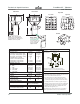
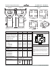
Performance characteristics
Batch size lb {g} 5.5 {2500} 5.5 {2500}
Maximum throughput rate lb/hr {kg/hr}
*
1000 {454} 800 {363}
Bin capacity - main ingredient ft
3
{liter} 1.6 {45.3} 2.7 {76.4}
Bin capacity - minor ingredient ft
3
{liter} 1.6 {45.3} 1.4 {39.6}
Maximum number of materials 4 6
Number of vertical discharge valves 4 6
Number/(size) of major bin valves 2 - (60 mm) 2 - (60 mm)
Number/(size) of minor bin valves 2 - (30 mm) 4 - (30 mm)
Dimensions inches {mm}
A - Height above mounting plate
†
57.50 {1461} 63.0 {1600}
B - Width 36.50 {926} 40.13 {1026}
C - Depth 40.83 {1037} 42.67 {1084}
D - Control height 8.25 {209.6} 8.25 {209.6}
E - Control width 9.25 {235.0} 9.25 {235.0}
F - Control depth 4.75 {120.6} 4.75 {120.6}
Weight lbs {kg}
Installed 320 {145} 400 {182}
Shipping 440 {200} 520 {236}
Voltage total amps
115V/1 phase/60 hz 6.3 6.3
230V/1 phase/50 hz 3.2 3.2
Compressed air requirements
Discharge valves 90 psi @ 0.2 ft
3
/min {6 bars @ 0.09
liters/sec}; 1/4 in. NPT fitting
Maximum loader sizes
15 inch loaders - number of loaders - 4 2
8 inch loaders- number of loaders - NA 4
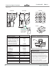
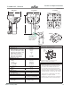
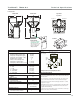
Top view
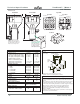
Front view
Side view
SPECIFICATION NOTES
*
Maximum throughput rates are based on 35 lb/ft
3
pel-
letized material and using all standard valve sizes. Use of
reducer inserts will lower the rate shown.
†
The optional flow control valve will mount inside the
chassis in the space of the manual slide valve. Conair
recommends using the optional flow control valve when
mounting the blender on a stand, surge bin or hopper.
‡ TB250-4 hopper positions two and four are supplied with
12-8 adapters with eight inch cover plates as standard.
TB250-6 hopper position two is supplied with a 12-8
adapter with an eight inch cover.
Specifications may change without notice consult with a
Conair representative for the most current information.
Control
MOUNTING INTERFACE
A
1
C
F
E
D
Position 1
Position 2
‡Position 4
‡Position 3
Dimensions
shown in
inches and {mm}.
4
3
Position 1
‡Position 4
‡Position 3
Position 2
4 position
6 position
‡Position 5
‡Position 6
NOTE: Side and front view
drawings are model TB250-4.
The bin positions change for a
TB250-6 see the top view.
B
3-5/32
diameter
{80}
16-5/32 {410}
12 {305}
8 {203}
4-1/16
{103}
8-1/16
{205}
16-5/32 {410}
2-1/16
{53}
2-1/16
{53}
8-1/16
{205}
4-1/16
{103}
Mixing chamber access door -
this side of the interface.
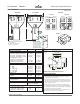
Purchase
the optional
material drain chute
that readily installs to the
chassis opening of the
blender for fast and
simple cleanout.
Mounting bolt hole size (8 holes) 9/16 inch {14.0 mm}.
Predrilled 8 x 8 and 12 X 12 mounting pattern as standard.
Drain chute
TrueBlend™ TB250-4
Technical Specifications
and TB250-6
TPBS026/0207
24
Edition: February 2008