WARNING - Reliance on this Manual Could Result in Severe Bodily Injury or Death! This manual is out-of-date and is provided only for its technical information, data and capacities. Portions of this manual detailing procedures or precautions in the operation, inspection, maintenance and repair of the product forming the subject matter of this manual may be inadequate, inaccurate, and/or incomplete and cannot be used, followed, or relied upon. Contact Conair at info@conairgroup.
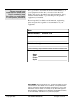
Please record your equipment’s model and serial number(s) and the date you received it in the spaces provided. It’s a good idea to record the model and serial number(s) of your equipment and the date you received it in the User Guide. Our service department uses this information, along with the manual number, to provide help for the specific equipment you installed. Please keep this User Guide and all manuals, engineering prints and parts lists together for documentation of your equipment.
INTRODUCTION . . . . . . . . . . . . . . . . . . .1-1 Purpose of the User Guide . . . . . . . . . . . . . . . . . . . . . . . . .1-2 How the Guide is Organized . . . . . . . . . . . . . . . . . . . . . . .1-2 Your Responsibility as a User . . . . . . . . . . . . . . . . . . . . . .1-2 ATTENTION: Read this so no one gets hurt . . . . . . . . . . .1-3 TABLE OF CONTENTS DESCRIPTION . . . . . . . . . . . . . . . . . . . .2-1 What is the Portable Chiller? . . . . . . . . . . . . . . . . . . . . . . .
TABLE OF CONTENTS OPERATION . . . . . . . . . . . . . . . . . . . . . . . . . . . .CONT’D PLC CONTROL______________________________________ Programming Settings . . . . . . . . . . . . . . . . . . . . . . . . . . .4-21 Changing Setpoint Temperature . . . . . . . . . . . . . . . . . . . .4-22 Resetting PID Settings . . . . . . . . . . . . . . . . . . . . . . . . . . .4-23 Changing High Temperature Deviation . . . . . . . . . . . . . .4-24 Setting Percent Glycol . . . . . . . . . . . . . . . . . . . . . . .
INTRODUCTION l Purpose of the User Guide . . . .1-2 l How the Guide is Organized . . .1-2 l Your responsibility as a user . .1-2 l ATTENTION: Read this so no one gets hurt . . . . . . . . . . .
PURPOSE OF THE USER GUIDE HOW THE GUIDE IS ORGANIZED YOUR RESPONSIBILITY AS A USER This User Guide describes Conair’s Portable Chillers and explains step-by-step how to install, operate, maintain and repair this equipment. Before installing this product, please take a few moments to read the User Guide and review the diagrams and safety information in the instruction packet. You also should review manuals covering associated equipment in your system.
We design equipment with the user’s safety in mind. You can avoid the potential hazards identified on this machine by following the procedures outlined below and elsewhere in the User Guide. ATTENTION: READ THIS SO NO ONE GETS HURT WARNING: Improper installation, operation, or servicing may result in equipment damage or personal injury.
WARNING: Hazardous substance When burned, Freon R22 refrigerant forms Phosgene gas. If the chiller is placed in the vicinity of equipment with combustible systems, the combustion air intake must be ducted in from the outside and sealed in such a manner as to prevent any refrigerant from entering the combustion chamber. Refer to the Material Safety Data Sheet for Freon R22 included in the appendix. This sheet explains the potential hazards and how to avoid them.
DESCRIPTION l What is the Portable Chiller? . . .2-2 l Typical Applications . . . . . . . . . .2-3 l Limitations . . . . . . . . . . . . . . . . .2-3 l How it Works: Water-cooled Portable Chiller . . . . . . . . . . .2-4 l How it Works: Air-cooled Portable Chiller . . . . . . . . . . .2-6 l Portable Chiller Features . . . . . .2-8 l Pump Curves . . . . . . . . . . . . . .
WHAT IS THE PORTABLE CHILLER? The Conair Portable Chillers provide self-contained sources of chilled water and are available in either water- or air-cooled models with ranges from 1.5 Hp to 30 Hp (approximate capacities of 1.5 tons to 30 tons of refrigeration). Pump selections are available to match most process flow and pressure requirements. The normal temperature range of discharge chilled water is 20°F to 70°F (7°C to 21°C).
The Conair Portable Chillers can be used anywhere a reliable source of process cooling water - with stable temperature control - is required. TYPICAL APPLICATIONS These portable chillers are available for cooling injection molding, blow molding, thermoforming, extrusion, air compressors, metal plating, anodizing, degreasing, heatset/web offset printing presses, and dryer after-coolers. Roll the air-cooled model next to the heat source, connect it, and plug it in. They can operate almost anywhere.
Process circulation HOW IT WORKS: WATER-COOLED PORTABLE CHILLERS 2 1 3 Type 1 3 1 2 3 1 2 2-4 Type 3 DESCRIPTION Portable Chillers Type 2 1 Hot fluid from the process enters the chiller through the From Process valve into the pump reservoir. 2 Pump draws water from pump reservoir and moves it through the strainer and flow switch to the evaporator. 3 Fluid is chilled in the evaporator and exits through the To Process valve and tube, returning to the process.
Refrigerant circulation HOW IT WORKS: WATER-COOLED PORTABLE CHILLERS 1 The evaporator extracts heat from the process fluid, causing the refrigerant to vaporize (evaporate) into a gas. 2 Vaporized refrigerant travels from the evaporator to the compressor, where the low pressure vapor is compressed into a high-pressure, high-temperature vapor. 3 The high-pressure, high-temperature vapor from the condenser to the receiver. 4 The high pressure vapor travels from the condenser to the receiver.
Process circulation HOW IT WORKS: AIR-COOLED PORTABLE CHILLERS 1 3 Type 1 2 3 1 2 Type 2 3 1 1 2 Type 3 2 3 2-6 DESCRIPTION Portable Chillers Hot fluid from the process enters the chiller through the From Process valve into the pump reservoir. Pump moves fluid from pump reservoir through evaporator where it is chilled. Fluid is chilled in the evaporator and exits through the To Process valve and tube, returning to the process.
HOW IT WORKS: AIR-COOLED PORTABLE CHILLERS Refrigerant circulation 1 The evaporator extracts heat from the process fluid, causing the refrigerant to vaporize (evaporate) into a gas. 2 Vaporized refrigerant travels to the compressor, where the low pressure vapor is compressed into a high-pressure, high-temperature vapor. 3 The high pressure vapor travels from the compressor through the condenser, where the fan cools and condenses the vapor into a high-temperature, high-pressure liquid.
PORTABLE CHILLER FEATURES Water-cooled Models Hot Gas Bypass valve Hot Gas Bypass valve Relief valve Condenser Relief valve Compressor Receiver Liquid line solenoid valve TX valve Process pump Evaporator Pump reservoir Filter dryer Type 1 Liquid line solenoid valve Type 3 Receiver Process pump Relief valve Compressor Condenser Recirculation pump Filter dryer TX valve Liquid line solenoid valve Pump reservoir Process pump Evaporator Type 2 2-8 DESCRIPTION Portable Chillers UGH024/1103
PORTABLE CHILLER FEATURES Air-cooled Models Hot Gas Bypass valve Condenser Fans Compressor Condenser Fan Receiver Process pump Type 1 Filter dryer Evaporator Pump reservoir Fan Evaporator Type 2 Hot Gas Bypass valve Process pump Condenser Compressor Temperature sensor TX valve Process pump Type 3 Pump reservoir UGH024/1103 Evaporator Recirculation pump Portable Chillers DESCRIPTION 2-9
PUMP CURVES SINGLE PUMP 15 Hp 10 Hp 5 Hp 3 Hp-PCW/A 3,5,7.5,10 & 15 only 3 Hp-PCW/A 20 & 25 only 7.5 Hp 2 Hp 1Hp 1.5 Hp 0.75 Hp Flow Rate (gpm) SPECIFICATION NOTES These pump curves are non-overloading using the service factor of the motors. Specifications may change without notice. Check with your Conair representative for the most current information.
1-7.5 Hp PUMP CURVES DUAL PUMP 5 Hp-PCW/A-5 & 7 only 5 Hp-PCW/A-15 only 3 Hp-PCW/A-3 only 7.5 Hp 3 Hp-PCW/A-5,7.5,10,15 & 20 only 1 Hp 1.5 Hp 2 Hp-PCW/A-3 only 5 Hp-PCW/A-10,15,20,25 & 30 only Flow Rate (gpm) 10-20 Hp 25 Hp-PCW/A-10 & 15 only 20 Hp-PCW/A-10 & 15 only 15 Hp-PCW/A-15 only 10 Hp-PCW/A-10 & 15 only 15 Hp-PCW/A-20, 25 & 30 only 10 Hp-PCW/A-20, 25 & 30 only Flow Rate (gpm) SPECIFICATION NOTES These pump curves are non-overloading using the service factor of the motors.
INSTALLATION l Unpacking the Boxes . . . . . . . . . .3-2 l Warnings and Cautions . . . . . . . . .3-3 l Preparing for Installation . . . . . . .3-4 l Making Process Plumbing Connections . . . . . . . . . . . . . . . .3-5 l Filling the Chiller . . . . . . . . . . . . . .3-6 l Checking Refrigerant Charge . . . .3-8 l Connecting the Main Power Source . . . . . . . . . . . . . . .3-9 l Checking Electrical Connections 3-10 TIC CONTROL l Checking Pump Rotation . . . . . .3-11 l Checking the Compressor . . . . .
UNPACKING THE BOXES The portable chiller comes fully assembled in a single crate. The Air cooled units are shipped without the casters attached. The casters must be attached during unpacking. CAUTION: Lifting Conair Portable Chillers are designed to easily roll on casters. If, for some reason you need to lift the chiller, take all precautions to avoid personal injury or damage to the chiller.
WARNING: Improper installation, operation, or servicing may result in equipment damage or personal injury. This equipment should only be installed, adjusted, and serviced by qualified technical personnel who are familiar with the construction, operation, and potential hazards of this type of machine. WARNINGS AND CAUTIONS All wiring, disconnects and fuses should be installed by qualified electrical technicians in accordance with electrical codes in your region. Always maintain a safe ground.
PREPARING FOR INSTALLATION Plan the location for the chiller and prepare the area properly. Position the chiller as close to the process machine as possible. Place the chiller in position near the process machine so that fluid lines can be connected from the process machine to the chiller and back. Chiller Process machine Alternate locations Make sure the area where the chiller is installed has: l A grounded power source. Check the chiller’s serial tag for the correct amps, voltage, phase, and cycle.
Warm fluid from process equipment enters the chiller at the From Process valve and chilled fluid returns to the process equipment through the To Process valve. 1 Remove the shipping plastic pipe plug from the female connections on the back of the portable chiller. 2 Make sure the male pipe threads are clean 3 4 Wrap threads with Teflon or pipe dope. MAKING PROCESS PLUMBING CONNECTIONS and new. Connect the From Process valve (Factory Optional) on the back of the chiller to the From Process tubing.
FILLING THE CHILLER The chiller is shipped without coolant. The chiller is filled manually during installation. Use water as the coolant down to 40°F (4°C). Below 40°F and down to 20°F (-7°C), use an ethylene glycol or propylene glycol solution (see Percent Glycol vs. Temperature chart). To fill with water: NOTE: If your chiller has the optional auto-fill reservoir, the level switch will automatically fill the reservoir with water as needed. 1 2 Attach water hose to Fill/Drain valve.
To fill with glycol solution: 1 Mix the glycol to the proper percentage. Use the table to determine the percentage (by volume) of glycol needed for the process temperature (in °F) you require. Mix the proper percentage of glycol with water.
CHECKING REFRIGERANT CHARGE All chillers are fully charged with refrigerant at the factory. Your chiller’s model nameplate identifies the type and amount of total refrigerant charge required. Check refrigerant charge while the chiller is running. Check the refrigerant charge through the sight glass. For watercooled models open the side panel for a short period of time (15 seconds maximum) and check the sight glass; for aircooled models, locate the sight glass through the wire mesh side panel.
WARNING: Improper installation, operation, or servicing may result in equipment damage or personal injury. This equipment should only be installed, adjusted, and serviced by qualified technical personnel who are familiar with the construction, operation, and potential hazards of this type of machine. CONNECTING THE MAIN POWER SOURCE All wiring, disconnects and fuses should be installed by qualified electrical technicians in accordance with electrical codes in your region. Always maintain a safe ground.
CHECKING ELECTRICAL CONNECTIONS WARNING: Electrical hazard Before performing any work on this item, disconnect and lock out electrical power sources to prevent injury from unexpected energization or startup. 1 2 Open electrical enclosure.* Check the short-to-ground with an ohm meter. Connect the ohm meter to each of the three terminal screws and to the grounding lug. Test all three for resistance. The minimum resistance to ground should be 1 megohm.
Check the rotation of the pump. Compare pump rotation to arrow direction on pump. If pump is not turning in proper direction, disconnect main power to chiller, swap any two incoming power wires; reapply main power. Check for leaks inside the chiller cabinet; fix any leaks and dry the inside of the chiller before proceeding. TIC CONTROL CHECKING PUMP ROTATION If alarm light comes on check the alarm description and follow troubleshooting guide for repair.
PLC CONTROL INITIALLY WARMING THE CHILLER WARNING: Initial startup Do not press any buttons after initially applying power to the chiller. Let the chiller set, undisturbed, for a minimum of 8 hours before starting the chiller. This is necessary to allow the crankcase heater to warm properly, and to prevent the refrigerant from pooling in the compressor. 1 Turn on main power source.
After the initial warm up, check for proper pump rotation. If the pump rotation is correct, all other 3-phase components will be in the proper rotation and do not need checked. Manually turn on the pump from the main screen: 1 PLC CONTROL CHECKING THE PUMP ROTATION Press the arrow pointing to Run on the screen. STATUS SETUP RUN ALM press arrow 2 Use the Scroll arrows to scroll through Run screens to the Manual Pump screen. Manual Pump ON OFF press arrow 3 Press the ON arrow.
PLC C ONTROL CHECKING FOR LEAKS After checking pump rotation, continue with startup by checking the chiller for leaks. Do this by turning on only the pump from the control and letting the pump run while checking the inside of the chiller. 1 Press the Next arrow on the control to move to the Main screen. The Main screen displays: STATUS 2 SETUP RUN ALM Press the Run arrow on the screen. STATUS SETUP RUN ALM press arrow 3 Press the Scroll arrows to scroll to the Manual Pump screen.
Only after you have checked for leaks and checked for pump rotation should you run the chiller. To initially run the chiller, from the main screen: 1 Press the Run arrow. STATUS SETUP RUN ALM PLC CONTROL INITIALLY RUNNING THE CHILLER press arrow The Run screen displays: RUN STOP PUMPDOWN press arrow 2 Press the RUN arrow. Verify that the chiller begins to run. Check that the Compressor lights and the Process Pump light on the control panel are lit.
STOPPING THE PLC CHILLER To stop the chiller, press the Stop Chiller button on the control panel. The compressor shuts off after a pumpdown and the pump shuts off 10 seconds later. This allows the chiller to pump down the refrigerant system and store the refrigerant in the receiver (water-cooled models) or condenser (air-cooled models. This prolongs the life of the compressor.
OPERATION l TIC Control Features . . . . . . . . . . . . . . . . . .4-2 l PLC Control Features . . . . . . . . . . . . . . . . .4-3 l Before Starting . . . . . . . . . . . . . . . . . . . . . .4-4 TIC CONTROL l Control Features . . . . . . . . . . . . . . . . . . . . .4-5 l Changing the Setpoint Temperature . . . . . . . . . . . . . . . . . . . . . . .4-6 l Stopping/Starting the Chiller . . . . . . . . . . . .4-6 l Menu Features . . . . . . . . . . . . . . . . . . . . . . .4-8 l Changing the Settings . . .
TIC CONTROL FEATURES The TIC control lets you view the status of the chiller and change settings. Display 3-digit screen shows Process temperature, Alpha Alarms and Operation indicators. Indicator light shows hot gas unloading. Main Menu Contents Setpoint Procedure Alarm Codes Informs user of types of alarms Status Lights For Pump, Hot Gas Bypass and Compressor On/Off Button Powers on/off the chiller Raise Button Increases values, and steps up through menus.
PLC CONTROL FEATURES Display Screen Shows status, setup and run modes Option Arrows Status Lights Show the status of the compressors, process pump, and alarm/shutdown Choose parameters displayed on the screen Scroll through the display screens PLC Indicator Lights Show power, program and service indications Stop Chiller Button Press to stop chiller UGH024/1103 Up / Down Scroll Arrows Navigation Buttons Save new settings, reset alarms and return to main screen Numerical Keypad Choose and change nume
BEFORE STARTING Before you start daily operation of the chiller, you need to perform scheduled preventative maintenance. Necessary maintenance is describe in the Maintenance section of this Users Guide. WARNING: Electrical hazard Be sure that power to the chiller is OFF when doing any maintenance on the chiller. Follow all safety rules when performing any maintenance on this equipment.
Menus on the Controller: The controller has information available in 5 areas. Four of them are user accessible. These are: the Main Menu, the Setpoint Menu, the Configuration menu and the Alarm Page. The service page also has additional parameters that are accessible in cases of need. GENERAL TIC CONTROL FEATURES Relaying Control information via three modes: The controller relays information via three modes. 1. The status lights indicate the state of the machine and its control components.
RESETTING THE TIC CONTROL AND POWER UP TIC CONTROL FEATURES CHANGING THE SETPOINT (SET) When powered, the chiller control automatically performs a bootup routine. When the bootup routine is complete, the display will alternate between “rst” and the actual to process temperature. To reset the control on power up, press the up and down arrow keys simultaneously for 1 second.
Starting/Stopping the Chiller Press the Stop/Start Chiller button. Check the Pump and Compressor lights on the control panel; they should turn on and off as the pump and compressor cycle on and off. The To Process temperature displays on the control, and is the real-time temperature. It should change as the chiller runs and cools the fluid. This is what the chiller controls. STARTING/ STOPPING THE CHILLER To safely stop the chiller at any time, press the Stop/Start Chiller button on the control panel.
TIC CONTROL CHANGING THE TEMPERATURE UNITS (UN) TIC CONTROL CHANGING THE LOW SETPOINT LIMIT (LTS) To return to the To Process Temperature screen from any other screen, press and hold the button for at least 5 seconds until the temperature displays. NOTE: Setpoint will show down to 20°F but it is limited by the variable to 40°F unless changed. 4-8 OPERATION The Temperature units parameter allows selection of the displayed temperature units. The available selection is either degrees Celsius or Fahrenheit.
The Process variable selector allows the operator to select the controlled temperature from the following: To Process, From Process and Average. The default is the average temperature and the tuning parameters are set up for this. If the chiller is used in a no tank system then the From process temperature should be selected. Depending on system size select the appropriate tuning parameter set, See Tuning the Chiller.
TIC TUNING THE CHILLER (PIT) CONTINUED Fast Responding System: Select the fast setting “FSt” for small systems*. Less than 250 pounds of water (30 gallons) and 2,000 pounds of steel might be considered a small system. This setting has the largest proportional band (4ºF), which allows a fast response to small deviations between the process variable and setpoint. This system is typical for small chillers with small molds or other process machinery.
The deviation temperature ignore time is the time from when a deviation from setpoint is sensed until it is displayed. The deviation from setpoint occurs when the actual temperature of the fluid is some value away from the setpoint (value is set by dt). The deviation temperature ignore time range is 0-600 seconds, the default is 300 seconds and should be sufficient for most applications. 1 Press the Enter key until the default configuration page Un appears on the screen.
TIC CONTROL CHANGING THE LOW TEMPERATURE ALARM SETPOINT (SPL) The low limit temperature alarm setpoint is the setpoint that protects the chiller from undershooting past the required process water temperature. The range for this setting is 19.479 and the default is 39. For most applications this value will need set about 3°F below the LTS value. 1 2 Press Menu button until UN is displayed. Press Enter again to display value of Low Limit Setpoint to raise and lower the low limitsetpoint temperature.
This is the temperature value that the actual temperature can be away from the setpoint. If the actual temperature is more than the deviation value away from the setpoint the Dtt will initiate and a passive alarm dtA will occur 300 seconds later. 1 2 Press the Enter key until the default configuration page Un appears on the screen. Toggle up/down buttons until display flashes dt, press “Enter”. Use the up/down buttons to set your desired deviations setpoint temperature.
TIC C ONTROL READING THE SOFTWARE VERSION (co1) TIC ALARMS The Version of the software is depicted by the c “xx” parameter. This “read only” parameter and depicts the version of the software that has been downloaded into the controller. This number will be a paramount importance in obtaining service support. EX CØ1 is version 01 of the chiller program. Alarm Stage When the controller senses an alarm, the specific alarm flashes alternating with the actual process variable on the display.
. PAL: (Pressure alarm low) flashes when the low refrigerant pressure switch has sensed low pressure for more than the low pressure ignore time (lpl). This is a cycling alarm up to three times per hour. TIC ALARMS CONTINUED Third type of Alarm Third type of alarm is a latching type. This alarm shuts down the compressor on t he first trip and must be manually reset upon correction of the fault condition. This high pressure and sensor failure alarms are of this type.
TIC ALARMS CONTINUED THS: Indicates that the compressor has shut down due to high temperatures to the process that could damage the compressor (Hts) FAL: (Flow alarm low) flashes when the process water flow switch has detected a low flow condition for longer than the low flow ignore timer (fsl). TAL: The low temperature alarm shuts down the compressor when the leaving water temperature sensor detects a temperature below the low temperature alarm setpoint(spl).
Plug in the power cord to restore power after any required maintenance. The chiller requires 15 minutes warmup time after it is plugged in for the crankcase heater to warm up. 1 PLC CONTROL POWERING UP Turn on the main power. The chiller control automatically performs its bootup routine.
PLC CONTROL VIEWING STATUS SCREENS After you have viewed all the Status screens and made any necessary changes to the Setup screens, you are ready to run the Chiller. To run the chiller from the main screen: 1 Press the Run arrow on the Main screen. STATUS SETUP RUN ALM press arrow 2 Press the RUN arrow. RUN STOP PUMPDOWN press arrow In Run mode the compressor cycles off at 4° below the setpoint if the load is too low for the hot gas to keep the compressor from shutting down.
The Status screens are read-only screens. You cannot make changes to these screens. To view the status screens: 1 Press the Status arrow on the Main screen. STATUS SETUP RUN ALM PLC CONTROL VIEWING STATUS SCREENS Press arrow 2 Use the scroll arrows to scroll through the status screens. Verify that the readings each screen displays are the ones you want. You cannot change the readings of the screens from the Status screens.
PLC CONTROL VIEWING STATUS SCREENS CONTINUED Temperature Set Point 45 F 45 F From Process Temp 60 F From Process Temp Shows the temperature of the fluid entering the chiller. Can display in degrees Fahrenheit or Celsius. Chiller % Loading 90% Percent chiller load Shows the current percent of chiller capacity being used. This percentage is a read-only value and changes as the chiller cycles. Water Level Level Okay Water level Displays the current water level status.
The PLC control allows you to program various parameters for the Chiller: l Temperature Setpoint The temperature you want the To Process liquid. l High Temperature Deviation Set the number of degrees the temperature can rise above the setpoint temperature without an alarm. l Percent Glycol by Volume Use when you use an ethylene glycol or propylene glycol solution to lower the To Process temperature. Changing the percent glycol automatically changes and displays the low temperature cutout, in °F.
PLC CONTROL CHANGING SETPOINT TEMPERATURE Use the Temperature Setpoint to set the temperature you want the water to be exiting the chiller at the To Process valve. To display the Setpoint temperature from the Main screen, press the Setup arrow. The Setpoint screen displays: Setpoint 500 F 10 C number flashes The current setpoint temperature displays in both Fahrenheit (F) and Celsius (C). The temperature in °F flashes. 1 Press the arrows to change the setpoint temperature.
Use the PID reset to return the control to the factory settings. Use this if the autotune does not give good values or good values are lost. To reset PID from the main screen: 1 PLC CONTROL RESETTING PID SETTINGS Press the Setup arrow. STATUS SETUP RUN ALM Press arrow 2 Press the Scroll arrows to scroll through the Setup screens. Stop when you get to the PID Reset screen.
PLC CONTROL CHANGING HIGH TEMPERATURE DEVIATION Decide how many degrees above the setpoint you want the chiller to deviate before an alarm occurs. To set the high temperature deviation: 1 Press the Setup arrow. STATUS SETUP RUN ALM press arrow Continue to press the arrow to scroll through the Setup screens. Stop when you get to the High Temp Dev screen. The current high temperature deviation number displays along with the - and +. The number flashes on the screen.
To set the percent ethylene glycol or propylene glycol solution determine the temperature of the process fluid you want. Use water as the coolant for chilling the process fluid down to 40°F (4°C). Below 40°F and down to 20°F (-7°C), use a glycol solution. Use the table to choose the proper percentage of glycol solution for the required temperature.
PLC CONTROL SETTING PERCENT GLYCOL 2 Press the Up/Down Scroll arrows to scroll through the setup screens. Stop when you get to the Percent Glycol screen: CONTINUED % E.G. BY VOL Low Temp Cutout NOTE: If you are using water as the coolant, set the Percent Glycol to zero on the control. 0% 36F number flashes The screen displays the percent of glycol by volume currently used. This number is flashing.
For the Air-cooled Portable Chillers you can choose the condenser pressures in PSIG at which the fan cycles on and off. To set the Fan Setpoints from the main screen: 1 Press the Setup arrow. STATUS PLC CONTROL SETTING FAN SETPOINTS SETUP RUN ALM Press arrow 2 Press the Scroll arrows to scroll through the Setup screens. Stop when you get to the PID Reset screen. 3 Press the Fans arrow. PID Reset DPS FANS Note: This screen is password protected.
PLC CONTROL SETTING FAN SETPOINTS 5 Press Enter to save the change. 6 Press the Escape/Previous Screen button to return to the main screen. Fan setpoints are not saved in retentive memory and are lost when power is disconnected. Factory default values are reloaded on power up. SELECTING THE TEMPERATURE SCALE You can choose to display the temperature in either Fahrenheit or Celsius. To select the temperature scale: 1 Press the Setup arrow.
Use the Auto Tune Mode to maintain the temperature setpoint and minimize overshooting it. To set Auto Tune the chiller must be in Run mode. To run the Chiller from the main screen: 1 Press the Run arrow on the Main screen. STATUS PLC CONTROL SETTING AUTO TUNE MODE SETUP RUN ALM press arrow 2 Note: This screen is password protected. You must have clearance to enter and change settings on this screen. Press the RUN arrow. RUN STOP PUMPDOWN press arrow 3 Press the Escape/Previous Screen button.
PLC CONTROL SETTING AUTO TUNE MODE The password screen displays. 4 Use the keypad to enter the password. 5 Press the Enter button to enter the 6 Press the Scroll arrows to scroll to the 7 Press the Tune arrow. The factory-set password is 999. CONTINUED password. Tune screen. TUNE TUNE ABORT Press arrow When the control begins tuning the screen displays TUNING message. The auto-tuning sequence takes about 15 seconds. The screen displays the ‘TUNE Tuning’ message.
You can select the discharge pressure setpoints in PSIG. To set the discharge pressure setpoints from the main screen: 1 Press the Setup arrow. STATUS SETUP RUN ALM Press arrow 2 PLC CONTROL SETTING DISCHARGE PRESSURE SETPOINT Press the Scroll arrows to scroll through the Setup screens. Stop when you get to the PID Reset screen. PID Reset DPS FANS Press arrow 3 Press the DPS arrow. The Discharge Pressure Setpoint screen displays.
PLC CONTROL SELECTING PID VALUES The PID values are set at the factory to default settings. The values should be changed only if the water regulator valve or the VFD are unable to maintain discharge pressure. To set the discharge pressure setpoints from the main screen: 1 Press the Setup arrow. STATUS SETUP RUN ALM Press arrow 2 Press the Scroll arrows to scroll through the Setup screens. Stop when you get to the PID Reset screen. PID Reset DPS FANS Press arrow 3 Press the PID Reset arrow.
To run or stop the pump from the main screen: 1 Press the arrow pointing to Run on the screen. STATUS SETUP RUN ALM press arrow PLC CONTROL MANUALLY STARTING/ STOPPING THE PUMP The first Run screen displays. 2 Use the Scroll arrows to scroll through 3 Press the arrow pointing to your choice. Run screens to the Manual Pump screen. If the pump is running and you want to stop it, press the arrow pointing to Off.
MAINTENANCE l Maintenance Features . . . . . . . .5-2 l Warnings and Cautions . . . . . . .5-3 l Preventative Maintenance Schedule . . . . . . . . . . . . . . . . .5-4 l PLC Control Entering Maintenance Screens . . . . . . .5-6 l Checking Electrical Connections . . . . . . . . . . . . . .5-7 l Cleaning the Evaporator or Water-cooled Condenser . . . .5-8 l Cleaning the Air-cooled Condenser . . . . . . . . . . . . . . . .5-9 l Checking the Refrigerant Charge . . . . . . . . . . . . . . . . . .
MAINTENANCE FEATURES Conair Series PCA/PCW need regular, scheduled maintenance for peak performance. To maintain the best performance of the chiller, it must be cleaned and inspected regularly. Maintenance includes a daily, monthly, and semi-annual schedule. Use this maintenance schedule as a guide. You may need to shorten the time of the maintenance schedule, depending on how often you use the chiller.
Follow all cautions and warnings when working on the equipment. WARNING: Improper installation, operation, or servicing may result in equipment damage or personal injury. WARNING AND CAUTIONS This equipment should only be installed, adjusted, and serviced by qualified technical personnel who are familiar with the construction, operation, and potential hazards of this type of machine.
PREVENTATIVE MAINTENANCE SCHEDULE To maintain the best performance, follow the maintenance schedule and record information in the Maintenance Log in the Appendix. l Daily, or as often as needed r Checking process fluid level in the pump tank Check the process fluid level in the water level gauge on the back of the chiller. If low, see Filling the Chiller, in the Installation section. r Verifying pump discharge pressure While the pump is running, check that the pump pressure gauges are within range.
r Checking electrical connections, amps, volts Make sure electrical connections are properly seated. See Checking Electrical Connections, in the Maintenance section. Check fan, compressor, and pump amps and volts. r Cleaning Wipe all external surfaces to maintain performance. r Inspecting condenser Check the condenser for adequate air flow or water flow. Check the condenser face for dirt and clogging. If dirt or clogs are present, clean the condenser.
PLC CONTROL ENTERING MAINTENANCE SCREENS Use the Maintenance screens to view cycling information. the cycle screens display the total cycles or hours since the initial assembly of the chiller. These numbers are only reset through the Conair screens by Conair Service personnel. To view the cycle information: 1 Press the Setup arrow. STATUS The Maintenance screens are password protected. You must have clearance to enter and change settings on these screens.
WARNING: Electrical hazard Before performing any work on this item, disconnect and lock out electrical power sources to prevent injury from unexpected energization or startup. CHECKING ELECTRICAL CONNECTIONS WARNING: Improper installation, operation, or servicing may result in equipment damage or personal injury. This equipment should only be installed, adjusted, and serviced by qualified technical personnel who are familiar with the construction, operation, and potential hazards of this type of machine.
CLEANING THE EVAPORATOR OR WATER- Minerals and other contaminant’s produce deposits, scales, slime, or algae on the heat transfer surfaces exposed to water. Fouled surfaces result in decreased cooling capacity. Implement a water treatment program to slow the fouling. CAUTION: Hot Surfaces Always protect yourself from hot surfaces when working on the Portable Chiller, especially when working on or around the compressor and condenser. These devices can reach up to 160 °F (71 °C).
WARNING: Electrical hazard Before performing any work on this item, disconnect and lock out electrical power sources to prevent injury from unexpected energization or startup. CLEANING THE AIR-COOLED CONDENSER CAUTION: Hot Surfaces Always protect yourself from hot surfaces when working on the Portable Chiller, especially when working on or around the compressor and condenser. These devices can reach up to 160°F (71°C). Allow these devices to cool before performing any maintenance or troubleshooting.
CHECKING THE REFRIGERANT CHARGE All chillers are fully charged with refrigerant at the factory. Your chiller’s model nameplate identifies the type and amount of total refrigerant charge required. WARNING: Refrigerant hazard Only certified refrigerant technicians should examine and correct problems involving the refrigerant circuit. WARNING: Hazardous substance When burned, Freon R22 refrigerant forms Phosgene gas.
WARNING: Electrical hazard Before performing any work on this item, disconnect and lock out electrical power sources to prevent injury from unexpected energization or startup. CHECKING RESERVOIR LEVEL Check the fluid level in the reservoir. The meniscus in the sight glass on the back of the chiller should be in line with the mark on the sight glass. To manually fill the reservoir: 1 2 Disconnect and lockout power to the chiller. Locate the fill/drain valve on the back of the chiller.
TROUBLESHOOTING l Before Beginning . . . . . . . . . . . . . . . . . . . . .6-2 l A Few Words of Caution . . . . . . . . . . . . . . .6-3 l Identifying the Cause of a Problem . . . . . . . . . . . . . . . . . . . . . .6-3 l TIC Control Input / Output . . . . . . . . . . . . . .6-4 l TIC Control Answering an Alarm . . . . . . . .6-5 l TIC Control Problems . . . . . . . . . . . . . . . . .6-6 l TIC Control Mechanical Conditions . . . . . .6-8 l PLC Control Answering Alarms . . . . . . . .
BEFORE BEGINNING You can avoid most problems by following the recommended installation, operation and maintenance procedures outlined in this User Guide. If you have a problem, this section will help you determine the cause and tell you how to fix it. Before you begin troubleshooting: r Find any wiring, piping, and assembly diagrams that were shipped with your equipment. These are the best reference for correcting a problem.
WARNING: Improper installation, operation, or servicing may result in equipment damage or personal injury. A FEW WORDS OF CAUTION This equipment should only be installed, adjusted, and serviced by qualified technical personnel who are familiar with the construction, operation, and potential hazards of this type of machine. All wiring, disconnects, and fuses should be installed by qualified electrical technicians in accordance with electrical codes in your region.
TIC CONTROL INPUT/OUTPUT As part of troubleshooting you need to know the status of the inputs and outputs. Open the electrical enclosure and check the status of the inputs and outputs. When they are in normal range, the numbers are highlighted. If the number is not highlighted, it is out of range. I Inputs 1 2 3 4 5 6 DAY Outputs Always refer to the wiring diagrams you received with your chiller to locate specific electrical components.
When an alarm condition occurs, the alarm light on the control panel lights. It stays lit until the alarm condition is corrected. If you have the optional audible alarm, pressing the Enter button silences the audible alarm. To find out what is causing the alarm, check the indicator lights on the control panel for the pump and compressor status. If the pump and compressor are both off, check the water tank level, flow valves, and the pump.
TIC CONTROL PROBLEMS Look here if the control panel is not lit, or if the power is on and the Portable Chiller will not run. Symptom Possible cause Solution The control is not lit and the chiller is not working. Power is not reaching the chiller. p Check the power cord and plug. Make sure the cord and plug are properly connected. p Make sure the main disconnect switch is on. p Check fuses and breakers. Replace or reset as required.
TIC CONTROL PROBLEMS Symptom Possible cause Solution The control is lit and there is no alarm condition. The compressor hums, but does not run. The input voltage is incorrect Check the main supply voltage. It must be within 10% of the nameplate rating. There is a phase loss. p Check the fuses on the main power supply. p Check the phase-to-phase voltages. p Check phase continuity through the compressor contactor. p Check the wiring at the compressor. Replace or repair as needed.
TIC CONTROL ALARM CONDITIONS Possible cause Solution High Deviation Load too high for chiller. Reduce load on chiller; if not able to reduce load, choose a chiller with more capacity. Low Deviation Insufficient loadfor the chiller The chille rneeds to loaded by at last 25 % of the chiller capacity for correct operation; adjust as necessary. Low Condensed water temperature or low ambient air tempera ture. This will create a low in discharge pres sure.
TIC CONTROL ALARM CONDITIONS Alarm Possible cause Solution High temperature temp > 75°F Alarm Shutdown “tAH” Load too high for chiller. Reduce load on chiller; if not able to reduce load, choose a chiller with more capacity. Refrigeration circuit not working properly. Check refrigerant circuit. See Checking Refrigerant charge, Section 3.
TIC CONTROL ALARM CONDITIONS Alarm Possible cause Solution Low Suction Pressure (pump is running and compressor is off) “PAL” No or low flow with a failed flow switch and Sensor. o Compressor suction valve is closed. Open valve. No load on the Chiller. Check process load for required load. Chiller may be oversized. Check To Process and From Process valves to see if they are open. o Check Flow switch and Sensor. Replace as needed. The Evaporator is fouled. Clean Evaporator.
TIC CONTROL ALARM CONDITIONS Alarm Possible cause Solution High Discharge Pressure (pump is running, compressor is off) PSH must be manually reset by depressing reset button on top of switch in chiller and acknowledge on face of controller Clogged/dirty air-cooled condenser. Clean the coil. See Cleaning the Air-cooled Condenser, in the Maintenance section. Blocked air flow to aircooled condenser. Move chiller or unblock air passageway.
TIC C ONTROL ALARM CONDITIONS 6-12 Alarm Possible cause Solution High Discharge Pressure, cont’d PSH Compressor discharge valve closed. Open valve. Overcharged with refrigerant. See Checking the Refrigerant Charge in the Maintenance section. Faulty water regulating valve. Repair or replace the valve. Faulty pressure switch. See Checking the Pressure Switches, in the Troubleshooting section.
TIC CONTROL ALARM CONDITIONS Alarm Possible cause Solution Sensor Failure SF2 The process temperature sensor failed Check with OHM meter and see if the resistance matches the table below. Replace if needed. Sensor wiring is incorrect or failed Check all wiring from terninal strip to sensor in question. Repair as necessary.
TIC CONTROL ALARM CONDITIONS Alarm Possible cause Solution High Temperature Safety Temp >95 F alarm The hot gas bypass valve is not working properly (possibly stuck open) Shut isolation valve to the Hot Gas Bypass solenoid. If the To Process temperature starts to go down, the solenoid valve is faulty. Have a certified refrigeration technician replace the solenoid valve. Load is too high for the chiller. Remove some load from the process.
TIC CONTROL ALARM CONDITIONS Alarm Possible cause Solution Flow fault (pump and compressor are off) “FAL” The To Process and/or From Process valves are closed. Open valve(s). The Optional Process Fluid strainer is clogged. Clean the strainer. Water level in reservoir is low. Fill the reservoir. See Making Process Plumbing Connections, in the Installation section. The evaporator is fouled. Clean Evaporator. See Cleaning the Evaporator or Water-cooled Condenser, in the Maintenance section.
TIC CONTROL ALARM CONDITIONS Alarm Possible cause Solution Low Temperature Alarm (tAL) Insufficient load for the chiller The chiller needs to be loaded by at least 25 % of the chiller capacity for correct operation adjust as necessary. Creates a low refrigerant disLow condensed water temperature or low ambi- charge pressure which nega tively affects the system. ent air temperature Adjust as necessary.
TIC CONTROL ALARM CONDITIONS Alarm Possible cause Solution Pump Overload (pump and compressor are off) Must be manually reset in control enclosure. Overload set incorrectly. Check table on wiring diagram for correct amperage. Adjust overload accordingly. Low supply voltage. o Faulty contactor Check line and load side of contactor. It should be less than 5 volt drop across the contactor. If it is not, replace the contactor. See Replacing the Contactor in the Troubleshooting section.
TIC CONTROL ALARM CONDITIONS Alarm Possible cause SOLUTION Compressor Overload (pump is running and compressor is off) Not displayed on alarm compressor light lit but compressor not on. Low supply voltage. o Faulty contactor. Check line and load side of contactor. It should be less than 5 volt drop across the contactor. If it is not, replace the contactor. See Replacing the Contactor in the Troubleshooting section. Faulty overload module. Check amp draw of circuit.
When an alarm condition occurs, the Alarm light on the control panel lights and the control screen displays the alarm message. Low Suction Pressure PLC CONTROL ANSWERING ALARMS Before an alarm can be reset with the acknowledge key, the alarm condition must be cleared. Refer to the Alarm table and the Troubleshooting tables to troubleshoot the alarm condition(s). After correcting the condition, remove the alarm from the screen.
PLC CONTROL ALARM CONDITIONS Low Temperature Cutout Higm Temp Safety (Temp >95 ° F) High Temperature Deviation Low Water Tank Level Flow Fault Low Suction Pressure Low Suction Pressure 2 6-20 TROUBLESHOOTING Before an alarm can be reset with the acknowledge key, the alarm condition must be cleared. To acknowledge an alarm is press and hold the Shift button for 3 seconds. When the temperature falls below the Low To Process Temperature cut out, the compressor shuts off.
PLC CONTROL ALARM CONDITIONS CONT’D If refrigerant discharge pressure (PT-2) goes above 270 psig (for water-cooled models) or 350 psig (for air-cooled models) the compressor shuts down. The Alarm light illuminates and the PLC indicates "High Discharge Pressure" for the compressor on a single compressor system and compressor 1 on a dual compressor system. The PLC will indicate "High Discharge Pressure 2" for compressor 2 on a dual compressor system.
PLC CONTROL ALARM CONDITIONS CONT’D Condenser Filter Fault Comp 1 Rotation Error Comp 2 Rotation Error Water-cooled chillers have a differential pressure switch (PDS-1) on the condenser water. This switch indicates a highpressure drop through the condenser and strainer, usually the result of a dirt strainer or fouled condenser. The alarm light (and strobe) illuminate and the PLC displays the message "Condenser Filter Fault". The compressor and pump(s) continue to run.
PLC CONTROL ALARM ERRORS Alarm Message Description Flow Fault There is low process fluid flow at the pump discharge. Low Suction Pressure The refrigerant pressure, measured at the inlet of compressor 1, is low. High Discharge Pressure The refrigerant pressure, measured at the inlet of compressor 1, is high. Process Pump Overload High amperage condition; the pump is drawing too much current.
PLC CONTROL ALARM HISTORY SCREENS The alarm history screens display the last 10 alarms that have occurred. They are listed in the order of newest to oldest. Scroll through the alarm history screens by pressing the scroll arrows. The Next arrow takes you back in time. The alarm screen displays the alarm number (1-10) and an alarm description. Pressing the Select Option arrows allows the operator to view the pressures and temperatures at time of the alarm.
PLC CONTROL ALARM SCREEN LEGEND UGH024/1103 Portable Chillers TROUBLESHOOTING 6-25
PLC CONTROL PROBLEMS Symptom Possible cause Solution The control is not lit and the chiller is not working. Power is not reaching the p Check the power cord and chiller. plug. Make sure the cord and plug are properly connected. p Make sure the main disconnect switch is on. p Check fuses and breakers. Replace or reset as required. See Replacing Fuses, in the Troubleshooting section. The correct power is not reaching the unit Check the voltage specification on the chiller nameplate.
PLC CONTROL PROBLEMS CONT’D Symptom Possible cause Solution The control is lit and there is no alarm condition. The compressor hums, but does not run. The input voltage is incorrect Check the main supply voltage. It must be within 10% of the nameplate rating. There is a phase loss. p Check the fuses on the main power supply. Replace or reset as required. See Replacing Fuses, in the Troubleshooting section. p Check the phase-to-phase voltages.
PLC CONTROL ALARM CONDITIONS Alarm Possible cause Low Water Tank Level alarm Water level in tank is low. Fill tank to proper level. See Checking Reservoir Level, in the Maintenance section. Inspect for leaks in the process piping. Repair as necessary. See Making Plumbing Connections, in the Installation section. Failed Level switch. Solution Check level gauge and compare it to status of the level switch by checking continuity of switch in electrical enclosure. Refer to wiring diagrams.
PLC CONTROL ALARM CONDITIONS Alarm Possible cause Solution Flow Fault alarm The To Process and From Process valves are closed. Open valve(s). The Process fluid strainer Clean the strainer. is clogged. UGH024/1103 Water level in reservoir is low and float switch failed. Fill the reservoir. See Making Process Plumbing Connections, in the Installation section. The evaporator is fouled. Clean Evaporator. See Cleaning the Evaporator or Water-cooled Condenser, in the Maintenance section.
PLC CONTROL ALARM CONDITIONS Alarm Low Suction Pressure alarm Possible cause Solution No or low flow with a failed flow switch and RTD. Check To Process and From Process valves to see if they are open. Check Flow switch and RTD. Replace as needed. Compressor suction valve is closed. Open valve. The Evaporator is fouled. Clean Evaporator. See Cleaning the Evaporator or Water-cooled Condenser, in the Maintenance section. Evaporator frozen.
PLC CONTROL ALARM CONDITIONS Alarm Possible cause High Discharge Pressure alarm Clogged/dirty air-cooled con- Clean the coil. See Cleaning the Airdenser. cooled Condenser, in the Maintenance section. Solution Blocked air flow to air-cooled Move chiller or unblock air passageway. condenser. Low condenser water flow or Check required flow; see Specifications in water too warm to waterthe Description section. cooled condenser. Blocked condenser water line Unblock line; open valve.
PLC CONTROL ALARM CONDITIONS 6-32 Alarm Possible cause Solution Comp 1 Rotation Error alarm Compressor 1 is wired incorrectly. Shut off chiller supply voltage. Switch any two leads: l at compressor if it was replaced. l at main terminal block if new unit installation. Turn chiller on. High pressure transducer is faulty. See Checking the Pressure Transducer, in the Troubleshooting section.
PLC CONTROL ALARM CONDITIONS Alarm Possible cause Solution Pump Overload alarm Overload set incorrectly. Check table on wiring diagram for correct full load amperage (FLA) draw. Adjust overload accordingly. Low supply voltage. o Faulty contactor Check line and load side of contactor. It should be less than 5 volt drop across the contactor. If it is not, replace the contactor. See Replacing the Contactor in the Troubleshooting section. Check supply voltage.
PLC C ONTROL ALARM CONDITIONS Alarm Possible cause Solution High Temperature Safety Temp >95 F alarm The hot gas bypass valve is not working properly (possibly stuck open) Shut isolation valve to the Hot Gas Bypass solenoid. If the To Process temperature starts to go down, the solenoid valve is faulty. Have a certified refrigeration technician replace the solenoid valve. Load is too high for the chiller. Remove some load from the process.
PLC CONTROL ALARM CONDITIONS Alarm Possible cause Solution Low Temperature Cutout alarm The hot gas bypass valve is not working properly (possibly stuck closed). If the To Process temperature starts to go down, the solenoid valve is faulty. Have a certified refrigeration technician replace the solenoid valve. Check voltage to coil; replace coil if needed. Fluid flow is insufficient. Check for plugged pipes, closed valves, or failed flow switch. Failed RTD or Temperature Transmitter.
PLC CONTROL ALARM CONDITIONS 6-36 Alarm Possible cause SOLUTION Compressor Overload alarm Overload set incorrectly. Check table on wiring diagram for correct rated load amperage (RLA) draw. Adjust overload accordingly. Low supply voltage. o Faulty contactor Check line and load side of contactor. It should be less than 5 volt drop across the contactor. If it is not, replace the contactor. See Replacing the Contactor in the Troubleshooting section. Faulty overload module.
PLC CONTROL ALARM CONDITIONS Alarm Possible cause Solution High Temperature Temp > 75°F for 5 min alarm Load too high for chiller. Reduce load on chiller; if not able to reduce load, choose a chiller with more capacity. Refrigeration circuit not working properly. Check refrigerant circuit. See Checking Refrigerant Charge, in the Installation section. Compressor malfunctioned. Check voltage to compressor. Check contact points on contactor. Replace if needed. Refrigeration charge low.
PLC CONTROL ALARM CONDITIONS Alarm Possible cause Solution Evaporator Filter Fault alarm Clogged strainer. Clean strainer; replace as needed. Evaporator fouled. 6-38 TROUBLESHOOTING Clean Evaporator. See Cleaning the Evaporator or Water-cooled Condenser, in the Maintenance section. A valve is closed in the process water flow piping. Check valves; open if closed. There is a PLC voltage problem. Check voltage (see electrical drawings). The differential pressure switch is faulty.
PLC CONTROL ALARM CONDITIONS Alarm Possible cause Solution Condenser Filter Fault alarm (Water-cooled models only) Clogged strainer. Clean strainer; replace as needed. The differential pressure switch is faulty. Check wiring and voltage; replace switch as needed. Other piping obstruction. Check that all piping is large enough to carry fluid. Replace any piping or conduit that is too small. Clean any clogs. Condenser fouled. Clean Condenser.
PLC CONTROL ALARM CONDITIONS 6-40 Alarm Possible cause Solution High Discharge Pressure 2 alarm Clogged/dirty air-cooled condenser. Clean the coil. See Cleaning the Air-cooled Condenser, in the Maintenance section. Blocked air flow to aircooled condenser. Move chiller or unblock air passageway. Low condenser water flow or water too warm to watercooled condenser. Check required flow; see Specifications in the Description section. Blocked condenser water line or valve closed.
PLC CONTROL ALARM CONDITIONS Alarm Possible cause Solution Low Suction Pressure 2 alarm No or low flow with a failed flow switch and RTD. Check To Process and From Process valves to see if they are open. Check Flow switch and RTD. Replace as needed. Compressor suction valve Open valve. is closed. The Evaporator is fouled. Clean Evaporator. See Cleaning the Evaporator or Water-cooled Condenser, in the Maintenance section.
PLC CONTROL ALARM CONDITIONS Alarm Possible cause SOLUTION Compressor Fault alarm Compressor module protector fault. See compressor manual accompanying this user guide. If necessary, call your Conair Service Representative. Compressor malfunctioned. Call your Conair Service Representative.
PLC CONTROL ALARM CONDITIONS Alarm Possible cause SOLUTION Compressor 2 Overload alarm Overload set incorrectly. Check table on wiring diagram for correct rated load amperage (RLA) draw. Adjust overload accordingly. Low supply voltage. o Faulty contactor Check line and load side of contactor. It should be less than 5 volt drop across the contactor. If it is not, replace the contactor. See Replacing the Contactor in the Troubleshooting section. Faulty overload module. Check amp draw of circuit.
PLC CONTROL ALARM CONDITIONS Alarm Possible cause Solution Compressor 2 Rotation Fault alarm Compressor 2 is wired incorrectly. Shut off chiller supply voltage. Switch any two leads: l at main terminal block if new unit installation. l at compressor if it was replaced. Turn chiller on. High pressure transducer is faulty. Check discharge pressure on the Status screen. See Checking the Pressure Transducer, in the Troubleshooting section.
PLC CONTROL ALARM CONDITIONS Alarm Possible cause Solution Fan Overload alarm Access door is open. Close access door. Overload switch has been Reset overload switch. manually shut off. Overload set incorrectly. Check table on wiring diagram for correct full load amperage (FLA) draw. Adjust overload accordingly. Low supply voltage. o Faulty contactor Check line and load side of contactor. It should be less than 5 volt drop across the contactor. If it is not, replace the contactor.
PLC CONTROL ALARM CONDITIONS Alarm Possible cause SOLUTION Discharge Pressure Sensor Failure alarm Wiring bad. Check wiring; correct as needed. There is RF interference. Check for any electromagnetic interference (for example, from radios). Remove any objects causing the problem. The sensor has been dam- Check discharge pressure status. aged. See Checking the Pressure Transducer, in the Maintenance section. Repair or replace the sensor. Wiring bad. Check wiring; correct as needed.
WARNING: Electrical hazard Before performing any work on this unit, disconnect and lock out electrical power sources to prevent injury from unexpected energization or startup. CHECKING AND REPLACING SWITCHES There is a flow switch in the process fluid line to verify flow. To replace a flow switch: 1 Disconnect and lockout power to the chiller. 2 Open the electrical enclosure and locate the 3 Check the switch. connection for the correct switch on the terminal switch.
REPLACING RTD PLC THE ONLY To replace the RTD: 1 Disconnect and lockout power to the chiller. 2 Disconnect the To Process tubing from the To Process connection. Fill / Drain valve Fill / Drain valve To Process connection 3 Open the Drain/Fill valve and drain water from the unit so the water level is lower that the RTD. Always refer to the wiring diagrams you received with your chiller to locate specific electrical components. 4 Open the side of the chiller.
The pump’s wet end (impeller, motor, and seal assembly) can be removed for service. 1 2 Disconnect and lockout power to the chiller. REMOVING PUMP COMPONENTS Open the drain/fill valve and drain the water from the chiller. Open this side Open this side Fill / Drain valve 3 4 Open the side of the chiller. 5 Remove the pump assembly. 6 Inspect, clean, and replace pump parts Remove the bolts connecting the pump assembly to the pump housing.
REPLACING FUSES WARNING: Electrical hazard Before performing any work on this unit, disconnect and lock out electrical power sources to prevent injury from unexpected energization or startup. To replace fuses: Always refer to the wiring diagrams you received with your chiller to locate specific electrical components. Control transformer primary fuses* 1 Disconnect and lockout power to the chiller. 2 Open the electrical enclosure and locate 3 Remove and replace fuses.
WARNING: Electrical hazard Before performing any work on this unit, disconnect and lock out electrical power sources to prevent injury from unexpected energization or startup. To replace contactor for the pump or compressor: 1 Disconnect and lockout power to the chiller. 2 Open the electrical enclosure and locate 3 Disconnect the wiring from the contactor. REPLACING THE CONTACTOR the correct contactor. Refer to the wiring diagrams you received with your chiller.
Conair has made the largest investment in customer support in the plastics industry. Our service experts are available to help with any problem you might have installing and operating your equipment. Your Conair sales representative also can help analyze the nature of your problem, assuring that it did not result from misapplication or improper use.
EQUIPMENT GUARANTEE Conair guarantees the machinery and equipment on this order, for a period as defined in the quotation from date of shipment, against defects in material and workmanship under the normal use and service for which it was recommended (except for parts that are typically replaced after normal usage, such as filters, liner plates, etc.). Conair’s guarantee is limited to replacing, at our option, the part or parts determined by us to be defective after examination.
MAINTENANCE LOG Date Reading Maintenance Item Compressor 1 Amps, 100% loaded Compressor 2 Amps, 100% loaded Discharge Pressure 1 Discharge Pressure 2 Suction pressure 1 Suction pressure 2 Evaporator water out temperature Process Water Pressure Condenser 1 Water Temperature, In/Out Condenser 2 Water Temperature, In/Out Condenser Water Pressure, In/Out Condenser 1 Fan Amps Condenser 2 Fan Amps Process Pump Amps Recirculation Pump Amps Unit Volts Primary Secondary Condenser Air Temp In Condenser Air Temp Out
PRESSURE TABLES Evaporator and Piping Pressure Drops Size 1 PCA/PCW-7.5 PCA/PCW-2 PCA/PCW-1.5 PCA/PCW-3 PCA/PCW-4 PCA/PCW-10, PCA-13 PCA/PCW-5 PCW-15 Flow Rate, GPM PCA/PCW-10 PCA/PCW-7.5 Size 2 PCA/PCW-5 PCA/PCW-5 PCA/PCW-20 PCA/PCW-15 PCA/PCW-3.
PRESSURE TABLES Evaporator and Piping Pressure Drops PCA/PCW-10 PCA/PCW-5 PCA/PCW-7.5 PCA/PCW-5 PCA/PCW-20 PCA/PCW-15 PCA/PCW-3.
PRESSURE TABLES Condenser and Piping Pressure Drops Size 1 PCW-1.5 PCW-2 PCW-3 PCW-7.5 PCW-4 PCW-5 PCW-10 PCW-15 Flow Rate, GPM PCA/PCW-10 PCA/PCW-7.5 Size 2 PCA/PCW-5 PCA/PCW-5 PCA/PCW-20 PCA/PCW-15 PCA/PCW-3.
Overhead piping installations above process connections require installing a check valve in the To Process line and a 12 inch (305 mm) riser with check valve and vacuum break in the From Process line to prevent siphoning when shutting down. Install a vent tube to 12 inches (305 mm) above the highest system point to prevent over pressurization. Maximum height of piping above process connections is 10 ft (3 m).
PARTS & DIAGRAMS UGH024/1103 Portable Chillers P/D-1