www.conairgroup.
Please record your equipment’s model and serial number(s) and the date you received it in the spaces provided. It’s a good idea to record the model and serial number(s) of your equipment and the date you received it in the User Guide. Our service department uses this information, along with the manual number, to provide help for the specific equipment you installed. Please keep this User Guide and all manuals, engineering prints and parts lists together for documentation of your equipment.
Ta b l e o f C o n t e n t s 1-1 I n t r o d u c t i o n Purpose of the user guide . . . . . . . . . . . . . . . . . . . . . . . . . . . . . . . . 1-2 How the guide is organized . . . . . . . . . . . . . . . . . . . . . . . . . . . . . . 1-2 Using the Dust Collector . . . . . . . . . . . . . . . . . . . . . . . . . . . . . . . . . 1-3 Your responsibilities as a user . . . . . . . . . . . . . . . . . . . . . . . . . . . . . 1-3 ATTENTION: Read this so no one gets hurt . . . . . . . . . . . . . . . . . . .
5-1 M a i n t e n a n c e Filter Chamber . . . . . . . . . . . . . . . . . . . . . . . . . . . . . . . . . . . . . . . . 5-2 Collection Chamber . . . . . . . . . . . . . . . . . . . . . . . . . . . . . . . . . . . . . 5-2 6-1 Tr o u b l e s h o o t i n g Before Beginning. . . . . . . . . . . . . . . . . . . . . . . . . . . . . . . . . . . . . . . 6-2 Before you begin troubleshooting . . . . . . . . . . . . . . . . . . . . . 6-2 A few words of caution . . . . . . . . . . . . . . . . . . . . . . . . . . . .
SECTION 1 Purpose of the user guide . . . . . . . . . . . . . . 1-2 How the guide is organized . . . . . . . . . . . . . 1-2 Using the Dust Collector . . . . . . . . . . . . . . . 1-3 Yo u r r e s p o n s i b i l i t i e s a s a u s e r . . . . . . . . . . . 1 - 3 AT T E N T I O N : Read this so no one gets hurt . . . . . . . .
Purpose of the User Guide This User Guide describes the Conair Dust Collector and explains stepby-step how to install, operate, maintain and repair this equipment. Before installing this product, please take a few moments to read the User Guide and review the diagrams and safety information in the instruction packet. You also should review manuals covering associated equipment in your system. This review won’t take long, and it could save you valuable installation and operating time later.
Using the Dust Collector • Vacuum receiver/loader • PD Pump(s) or RG Pump(s) • Central loading control(s) Separate instructions are provided for these devices and should be referred to as needed to fully understand the operation of the entire system. Yo u r R e s p o n s i b i l i t y a s a U s e r You must be familiar with all safety procedures concerning installation, operation and maintenance of this equipment.
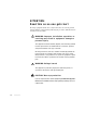
AT T E N T I O N : Read this so no one gets hurt We design equipment with the user’s safety in mind. You can avoid the potential hazards identified on this machine by following the procedures outlined below and elsewhere in the User Guide. WA R N I N G : I m p r o p e r i n s t a l l a t i o n , o p e r a t i o n , o r servicing may result in equipment damage or p e r s o n a l i n j u r y.
SECTION 2 What is the Dust Collector?. . . . . . . . . . . . . 2-2 Specifications: Dust Collector DC1 and DC2 . . . . . . . . . . . . . . . . . . .
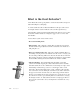
What is the Dust Collector? Conair Dust Collectors keep your plant free of air-born dust and fines and prevent dust from fouling the vacuum pump. A central vacuum dust collector allows dust filtration to take place at floor level. An air-tight collection container makes the removal of fines quick and easy. Automatic filter cleaning is standard, lengthening the time between service requirements. DC1 and DC2 models use an integrated “popper valve” to remove dust from the filter.
Specifications: Dust Collector DC1 and DC2 out in A B Model DC1 and DC2 SPECIFICATION NOTES: * Model DC1 works with Conair pump models RG-1-3, RG1-6, PD3, PD5, and PD7.5. Model DC2 works with RG1-11, RG2-16, PD10, PD15 and PD25. Specifications can change without notice. Check with a Conair representative for the most current information. Description l 2-3 2 Description MODELS DC1 DC2 Performance Characteristics Pump size range Hp {kW} * 3-7.5 {2.2-5.6} 10-25 {7.5-18.7} Vacuum line size OD in {mm} 1.
2-4 l Description
SECTION 3 Installation Preparing for installation - Location . . . . . . . 3-2 Installation. . . . . . . . . . . . . . . . . . . . . . . . 3-2 Optional Mounting . . . . . . . . . . . . . . . . 3-2 Va c u u m L i n e C o n n e c t i o n s . . . . . . . . . . . 3 - 3 Dust Return Line Connection . . . . . . . . . 3-4 Compressed Air Connections . . . . . . . . . 3-5 Electrical Connections . . . . . . . . . . . . . 3-5 Installation l 3-1 3 Installation Mounting . . . . . . . . . . . . . . . . . . . . . .
WARNING: You are responsible for the structural integrity of this installation. Preparing for Installation Location When using the manual dump type dust collector, it is best located near the vacuum pump. When using the automatic unload/reload dust collector, it is better to locate it near the loader that is receiving the dust. If neither location is convenient, then locate the dust collector anywhere along the vacuum line between the loader and pump assembly.
Installation (continued) Va c u u m L i n e C o n n e c t i o n s The vacuum line from the loader connects to the central separating section tangential entry tube. The vacuum line to the pump connects to the 3-way vacuum breaker valve which is installed in the center of the filter chamber. To Other Loaders Using Same Material To Material Supply Floor Stand Collection Chamber ✐ NOTE: Vacuum pump shown above is 180º out of position.
Installation (continued) Dust Return Line Connection For the automatic unload/reload type dust collectors, a “Y” diverter tube is included and should be installed as close as possible to the main material loader. Horizontal positioning of the “Y” diverter tube is best. The dust return line is a 1.5 inches {38.
Installation (continued) Compressed Air Connections Connect a compressed air line (80-100 psi) to the inlet of the solenoid valve which is located on the mounting plate of the filter chamber. An air line is connected from the solenoid to the vacuum breaker valve within the filter chamber. If the automatic unload/reload section is used, a line will also be ran to the solenoid valve mounted on the outside of the reload control. Compressed air must be filtered free of moisture.
3-6 l Installation
SECTION 4 Operation M a n u a l U n l o a d Ty p e . . . . . . . . . . . . . . . . . . 4 - 2 A u t o m a t i c U n l o a d / R e l o a d Ty p e . . . . . . . . . . .
M a n u a l U n l o a d Ty p e The internal 3-way vacuum valve is energized simultaneously with the vacuum pump. This allows a vacuum to be drawn through the dust collector, tubing and loader, starting the conveying cycle. During the conveying cycle, dust laden air enters the filtering section of the dust collector and the dust is separated from the air stream tangentially. This dust is deposited in the manual dump container below the filter chamber.
SECTION 5 Maintenance Fi l t e r C h a m b e r . . . . . . . . . . . . . . . . . . . . . 5 - 2 Collection Chamber . . . . . . . . . . . . . . . . . .
Filter Chamber Located within the filter chamber is a dry cartridge type filter. Regular filter servicing is required. Time between servicing depends on the pound/hour capacity of the loading system and the type of material used. Some indications of when to clean or change a filter are an increase in the normal conveying vacuum, surging or line blockage or a significant increase in load time (by 20 seconds or more).
SECTION 6 Tr o u b l e s h o o t i n g Before Beginning . . . . . . . . . . . . . . . . . . . . 6-2 Before you begin troubleshooting . . . . . . 6-2 A few words of caution . . . . . . . . . . . . . 6-2 Tr o u b l e s h o o t i n g . . . . . . . . . . . . . . . . . . . .
Before Beginning You can avoid most problems by following the recommended installation and maintenance procedures outlined in this User Guide. If you do have a problem, this section will help you determine what caused it and how to fix it. Before you begin troubleshooting: ❏ Find the wiring diagrams that were shipped with your equipment. These diagrams are the best reference for correcting a problem.
Tr o u b l e s h o o t i n g Solution Sluggish conveying, excessive load time, higher than normal conveying vacuums. The internal filter is clogged. Clean internal filter, replace as necessary. Excessive load time, low vacuum. Vacuum leak in material, vacuum or dust return lines. Seal “O” ring couplings, check hose clamps. 3-way vacuum valve is leaking. Increase air pressure 80-100 psi, clear obstructions. 3-way vacuum valve is inoperative or ineffective.
Additional manuals and prints for your Conair equipment may be ordered through the Customer Service or Parts Department for a nominal fee. Most manuals can be downloaded free of charge from the product section of the Conair website. www.conairgroup.com We ’ r e H e r e t o H e l p Conair has made the largest investment in customer support in the plastics industry. Our service experts are available to help with any problem you might have installing and operating your equipment.
Equipment Guarantee Conair guarantees the machinery and equipment on this order, for a period as defined in the quotation from date of shipment, against defects in material and workmanship under the normal use and service for which it was recommended (except for parts that are typically replaced after normal usage, such as filters, liner plates, etc.). Conair’s guarantee is limited to replacing, at our option, the part or parts determined by us to be defective after examination.