www.conairnet.
Please record your equipment’s model and serial number(s) and the date you received it in the spaces provided. It’s a good idea to record the model and serial number(s) of your equipment and the date you received it in the User Guide. Our service department uses this information, along with the manual number, to provide help for the specific equipment you installed. Please keep this User Guide and all manuals, engineering prints and parts lists together for documentation of your equipment.
Ta b l e o f C o n t e n t s 1-1 I n t r o d u c t i o n Purpose of the user guide . . . . . . . . . . . . . . . . . . . . . . . . . . . . . . . . 1-2 How the guide is organized . . . . . . . . . . . . . . . . . . . . . . . . . . . . . . 1-2 Your responsibilities as a user . . . . . . . . . . . . . . . . . . . . . . . . . . . . . 1-3 ATTENTION: Read this so no one gets hurt . . . . . . . . . . . . . . . . . . . 1-4 2-1 D e s c r i p t i o n What is the WSB/GB retrofit control? . . . . . . . . . . . . . . .
A Appendix We’re here to help . . . . . . . . . . . . . . . . . . . . . . . . . . . . . . . . . . . . . A-1 How to contact customer service . . . . . . . . . . . . . . . . . . . . . . . . . . A-1 Before you call... . . . . . . . . . . . . . . . . . . . . . . . . . . . . . . . . . . . . . . A-1 Equipment guarantee . . . . . . . . . . . . . . . . . . . . . . . . . . . . . . . . . . A-2 Performance warranty . . . . . . . . . . . . . . . . . . . . . . . . . . . . . . . . . . A-2 Warranty limitations . . . . . .
SECTION 1 Purpose of the user guide . . . . . . . . . . . . . . 1-2 How the guide is organized . . . . . . . . . . . . . 1-2 Yo u r r e s p o n s i b i l i t i e s a s a u s e r . . . . . . . . . . . 1 - 3 AT T E N T I O N : Read this so no one gets hurt . . . . . . . .
Purpose of the User Guide This User Guide describes the Conair WSB/GB Retrofit Control and explains step-by-step how to install the control. Before installing this product, please take a few moments to read the User Guide and review the diagrams and safety information in the instruction packet. You also should review manuals covering associated equipment in your system. This review won’t take long, and it could save you valuable installation and operating time later.
Yo u r R e s p o n s i b i l i t y a s a U s e r • Thorough review of this User Guide, paying particular attention to hazard warnings, appendices and related diagrams. • Thorough review of the equipment itself, with careful attention to voltage sources, intended use and warning labels. • Thorough review of instruction manuals for associated equipment. • Step-by-step adherence to instructions outlined in this User Guide.
AT T E N T I O N : Read this so no one gets hurt We design equipment with the user’s safety in mind. You can avoid the potential hazards identified on this machine by following the procedures outlined below and elsewhere in the User Guide. WA R N I N G : I m p r o p e r i n s t a l l a t i o n , o p e r a t i o n , o r servicing may result in equipment damage or p e r s o n a l i n j u r y.
SECTION 2 What is the WSB/GB retrofit control? . . . . . . 2-2 Ty p i c a l a p p l i c a t i o n s . . . . . . . . . . . . . . . . . . 2 - 2 How it works . . . . . . . . . . . . . . . . . . . . . .
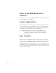
What is the WSB/GB Retrofit Control? The retrofit control converts the WSB/GB thumbwheel controller to the new touch screen TrueBlend control technology. Ty p i c a l A p p l i c a t i o n s The WSB/GB Retrofit Control is used with existing WSB/GB blenders of all sizes to convert the blender’s existing thumbwheel controller to the TrueBlend touch screen control technology. Both four component and twelve component blender configurations are supported with a six component limitation.
SECTION 3 Installation Unpacking the boxes . . . . . . . . . . . . . . . . . 3-2 Preparing for installation . . . . . . . . . . . . . . 3-3 or standard valves . . . . . . . . . . . . . . . . 3-4 Adding a load cell adapter . . . . . . . . . . . . . 3-5 Mixer sensor modification (GBM and WSBM). . 3-6 Mixer sensor modification (100 -1800) . . . . . 3-7 Removing the WSB/GB thumbwheel control . . 3-8 Connecting the WSB/GB convertor box . . . . . 3-9 Te s t i n g t h e i n s t a l l a t i o n . . . . . . . . . .
Unpacking the Boxes The WSB/GB retrofit control comes in two boxes. The boxes should include: 1 WSB/GB converter box 2 6 M cable for TB operator interface 3 TrueBlend touch screen operator panel 4 Load cell adapter (if the retrofit control is to be placed on the WSBM/GBM or WSB/GB100 model.
Preparing for Installation The WSB/GB retrofit control is easy to install if you plan the location and prepare the unit properly. 1 Before you plug in the WSB/GB converter box: WARNING: The load cell adapter must be placed between the existing load cell cable and the load cell connection on the retrofit kit before the control is powered up. If the adapter is not in place and the unit is powered up the WSB/GB retrofit box will be damaged.
Determining if your blender has p u l s i n g va l v e s o r s t a n d a r d va l v e s 1. Listen as the blender with your original control connected operates. If you hear a rapid pulsing sound you have pulsing valves. If you still are not sure proceed to step 2. CAUTION: Always disconnect and lock out the main power sources before accessing any part of the blender. Moving parts and electrical power can cause severe personal injury. 2. Visually inspect the valves.
Adding a Load Cell Adapter IMPORTANT! WSB/GB micro blenders and 100 model blenders require a load cell adapter to be placed between the existing load cell cable and the load cell connections on the retrofit convertor box. WARNING: Models GBM/WSBM micro blenders and 100 model blenders require a load cell adapter to be placed between the existing load cell cable and the load cell connections on the retrofit control before the control is powered up.
Mixer Sensor Modification For Blender Models: micro (GBM or WSBM) It is necessary to make a mixer sensor wiring modification to change the mixing chamber level sensor from normally opened (N.O.) to normally closed (N. C.). CAUTION: Always disconnect and lock out the main power sources before making electrical connections. Electrical connections should be made only by qualified personnel.
Mixer Sensor Modification For Blender Models: 100, 200, 400, 900 and 1800 The following steps will change the mixing chamber level sensor from normally opened (N.O.) to normally closed (N.C.). CAUTION: Always disconnect and lock out the main power sources before making electrical connections. Electrical connections should be made only by qualified personnel. White wire 1 See the illustration to the right Mixing and locate the male plug that connects to the controller.
Removing the WSB/GB Thumbwheel control CAUTION: Always disconnect and lock out the main power sources before making electrical connections. Electrical connections should be made only by qualified personnel. ✒ TIP: It may help you to know that, the WSB/GB 1 Record the model number and series of the WSB/GB control you will be removing. IMPORTANT you will need this information to set up the TrueBlend touch screen control. See the section entitled, “Testing the Installation,” in this section.
Connecting the WSB/GB Retrofit converter box CAUTION: Always disconnect and lock out the main power sources before making electrical connections. Electrical connections should be made only by qualified personnel. The retrofit converter box has the same input/output connections as the WSB/GB thumbwheel control. It will be necessary to make these connections to the retrofit converter box to operate the new touch screen control. 1 Lift the WSB/GB converter box and position it onto the blender control shelf.
Connecting the WSB/GB Retrofit c o n v e r t e r b o x (continued) CAUTION: Always disconnect and lock out the main power sources before making electrical connections. Electrical connections should be made only by qualified personnel. 4 Connect the level sensor cable from the mix chamber to the receptacle labeled “Mixer Level Sensor” on the control box. The cable is a threeprong, twist lock connector.
Connecting the WSB/GB Retrofit c o n v e r t e r b o x (continued) Valve Position 3 Valve Position 4 Pulse Valve Pulse Valve 230V 230V Standard Valve ✐ NOTE: This area of the control will only be seen on WSB/GB retrofit converter boxes that have been ordered to be placed on a blender that has pulsed valves.
Connecting the WSB/GB Retrofit c o n v e r t e r b o x (continued) ✐ NOTE: Step 8 only needs to be performed on blenders that have pulsing valves. See the section entitled, “Determining if your Blender has Pulsing Valves or Standard Valves,” in this manual. 8 Push the red slide switches into the correct position for Valve position 3 and Valve Position 4.
Connecting the WSB/GB Retrofit c o n v e r t e r b o x (continued) ✐ 10 NOTE: You cannot control more than six components with the TrueBlend Retrofit Kit. Plug feeders (if present) into the outlet receptacles. 11 Power Feeder Fuse Feeders 3&4 Ethernet Solenoid Valves Main Fuse 230V Feeders 5&6 On Off Feeder Power 10 12 11 Push the red slide switch for the feeders into the correct position. On a 4position control the feeders operate as position 3 and 4.
Te s t i n g t h e I n s t a l l a t i o n You have completed the installation. Now it’s time to make sure everything works. 1 Make sure the bins are full of material. 2 Turn on the main power to the blender 3 Flip the toggle switch on the front of the WSB/GB Retrofit Converter Box to the ON position. 4 Set up the TrueBlend touch screen operator panel for the appropriate model, as recorded earlier. See the chart below. To access the screen on the TrueBlend to make this selection see the TrueBlend Manual.
SECTION 4 Tr o u b l e s h o o t i n g DIAGNOSTICS Tr o u b l e s h o o t i n g . . . . . . . . . . . . . . . . . . . . 4 - 2 R E PA I R Replacing fuses . . . . . . . . . . . . . . . . . . . .
Tr o u b l e s h o o t i n g The troubleshooting information contained in this section applies to the WSB/GB retrofit control. You may also need to refer to your WSB/GB Blender manual and your TrueBlend Manual for more detailed troubleshooting pertaining to the blender or the touch screen control. Problem Possible cause Solution The WSB/ GB retrofit control will not power up. The main fuse on the WSB/GB retrofit has blown. Replace the fuse labeled main.
Replacing Fuses 1 Disconnect and lockout the main power supply. 2 Check the fuse. If necessary, pull the fuse out and replace it with a fuse of the same type and rating.
Additional manuals and prints for your Conair equipment may be ordered through the Customer Service or Parts Department for a nominal fee. Most Conair manuals is also available on line at www.conairnet.com, visit the product section and the archive manual section of the Conair web site. We ’ r e H e r e t o H e l p Conair has made the largest investment in customer support in the plastics industry.
Equipment Guarantee Conair guarantees the machinery and equipment on this order, for a period as defined in the quotation from date of shipment, against defects in material and workmanship under the normal use and service for which it was recommended (except for parts that are typically replaced after normal usage, such as filters, liner plates, etc.). Conair’s guarantee is limited to replacing, at our option, the part or parts determined by us to be defective after examination.