www.conairnet.com USERGUIDE SYSTEM CONFIGURATION for S900II robots Software Version 1.0 WARNING - Reliance on this Manual Could Result in Severe Bodily Injury or Death! This manual is out-of-date and is provided only for its technical information, data and capacities.
System Configuration S900II I – Memory I – MEMORY I – 1. Accessing the memory After accessing ”Memory Management” by pressing [Memo_M] (programming menu), pressing the [M_Read] key gives access to the read (or modification) function of the user and system RAM or EEPROM memory (at the address of the memory box by default if necessary). The address of the area at which reading is to begin is given in hexadecimal (0 to F) using the numerical keypad and the first row of alphanumerical keys of the keyboard.
System Configuration S900II I – Memory * The function keys F1 to F5 : [Address] to change the address. [Modif] to change the contents of the memory area displayed (word). [Search] to search for a particular word (e.g. : FA1B) [Print] to print the memory contents from the displayed address (in order to search for the incorrect instructions which will be printed as ????). [StopPr] to stop sending the memory contents to the printer.
System Configuration S900II I – Memory I – 2. Memory areas I – 2. 1.
System Configuration S900II I – Memory I – 2. 2.Program addressing in memory The PRG and PLC programs are stored in the RAM memory, starting from the address 0xB300. The maximum length of a PRG is 12286 bytes ; 4096 bytes for a PLC. This area reserved for the permanent storage varies depending on the option 32 to 128 Kbytes. So that it remains compatible with previous software versions, the RAM if formatted with 0xFFFF like an EEPROM.
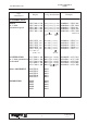
System Configuration S900II Block number I – Memory Contents Address in Hexadecimal F10 C0000 Messages in language 1 F10 CEBEF F10 CEBF0 Messages in language 2 F10 DD7DF F10 DD7E0 Font robot 1 F10 DE7EF F10 DE7F0 Font robot 2 7th block F10 DF7FF F10 DF800 Messages Code converter table IMM 1 F10 DF9FF F10 DFA00 Code converter table IMM 2 F10 DFBFF F10 DFC00 Code converter table Printer 1 F10 DFDFF F10 DFE00 Code converter table Printer 2 F10 DFFFF F10 E0000 SEPRO parameters 8th block Parameters and
System Configuration S900II I – Memory I – 3. Specific information These are directly accessed using the Memory Read function followed by the request [Address] and a letter : – to access the memory area containing the passwords. – to access the memory area containing the serial number and the type of robot. 15 B2A0 B2A2 B2A4 B2A6 B2A8 B2AA B2AC B2AE B2B0 B2B4 B2E0 B2E2 B2E4 B2E6 B2E8 B2EA B2EC B2EE 0 00 00 00 04 00 00 00 00 00 00 00 00 00 D2 00 00 00 00 00 00 Password to access edition (....
System Configuration S900II II – Instruction codes II – INSTRUCTION CODES II – 1. Part programs Type of Instruction ACTION Display Codop (hexadecimal) ACT 00 (to 99) * A000 [oper. 16 bits] Examples A000000C = ACT12 Action No. OUTPUT OUT 000 (to 255) * A001 [oper. 16 bits] A0010050 = OUT080 Output No. INPUT Normal IN 000 (to 255) INPUT Reverse IN/000 (to 255) TIMER TIME 001 to 999 A002 [oper. 16 bits] A002000A = IN010 Input No. A003 [oper. 16 bits] A0030020 = IN/032 Input No.
System Configuration S900II II – Instruction codes Type of Instruction Display Codop (hexadecimal) Examples FUNCTIONS (FUNC) SPEED in % of the parametered speed VEL.X 001 to 100 VEL.Y 001 to 100 VEL.Z 001 to 100 VEL.B 001 to 100 VEL.C 001 to 100 B000[oper.4bits][oper.12bits] B001[oper.4bits][oper.12bits] B002[oper.4bits][oper.12bits] B003[oper.4bits][oper.12bits] B004[oper.4bits][oper.12bits] B0000062 = VEL.X 098 B001000A = VEL.Y 010 B0020012 = VEL.Z 018 B0030064 = VEL.B 100 B004A032 = VEL.
System Configuration S900II Type of Instruction II – Instruction codes Display Codop (hexadecimal) SLA.X 001 to 100 SLA.Y 001 to 100 SLA.Z 001 to 100 SLA.B 001 to 100 SLA.C 001 to 100 B020 [oper. 16 bits] B021 [oper. 16 bits] B022 [oper. 16 bits] B023 [oper. 16 bits] B024 [oper. 16 bits] Examples MOTORIZED MOTIONS SLOW APPROACH in % of the maximum parametered speed B0200026 = SLA.X 026 B0210034 = SLA.Y 034 B0220090 = SLA.Z 090 B0230100 = SLA.B 100 B0240010 = SLA.
System Configuration S900II II – Instruction codes Type of Instruction CHECKING Display Codop (hexadecimal) Examples X.CTL_R Angle Y.CTL_R Angle Z.CTL_R Angle B.CTL_R Angle C.CTL_R Angle C130[oper.8bits][oper.24bits] C131[oper.8bits][oper.24bits] C132[oper.8bits][oper.24bits] C133[oper.8bits][oper.24bits] C134[oper.8bits][oper.24bits] SAP Marker No. TEACHING C Teach Previous instruction Angle in 1/10 deg. [oper.8bits]AAAAAA Instruction code C13000000664=X.CTL.R00163.6 C131000F423F=Y.CTL.R9999.
System Configuration S900II II – Instruction codes Type of Instruction Display Codop (hexadecimal) Examples RELATIVE X.REL_R WW *nn Y.REL_R WW *nn Z.REL_R WW *nn B.REL_R WW *nn C.REL_R WW *nn C320 [oper. 16 bits] C321 [oper. 16 bits] C322 [oper. 16 bits] C323 [oper. 16 bits] C324 [oper. 16 bits] C3200001 = X.REL.R WW01 CHECKING X.CTL_R WW *nn Y.CTL_R WW *nn Z.CTL_R WW *nn B.CTL_R WW *nn C.CTL_R WW *nn C330 [oper. 16 bits] C331 [oper. 16 bits] C332 [oper. 16 bits] C333 [oper. 16 bits] C334 [oper.
System Configuration S900II II – Instruction codes Type of Instruction Display Codop (hexadecimal) Examples LINEAR POS_ANA X = POS ANA + distance Y = POS ANA + distance Z = POS ANA + distance B = POS ANA + distance C = POS ANA + distance C060 [oper. 32 bits] C061 [oper. 32 bits] C062 [oper. 32 bits] C063 [oper. 32 bits] C064 [oper. 32 bits] POS_NUM X = POS NUM + distance Y = POS NUM + distance Z = POS NUM + distance B = POS NUM + distance C = POS NUM + distance C070 [oper. 32 bits] C071 [oper.
System Configuration S900II Type of Instruction II – Instruction codes Display Codop (hexadecimal) ROTATING POS_ANA X = POS ANA + angle Y = POS ANA + angle Z = POS ANA + angle B = POS ANA + angle C = POS ANA + angle C160 [oper. 32 bits] C161 [oper. 32 bits] C162 [oper. 32 bits] C163 [oper. 32 bits] C164 [oper. 32 bits] POS_NUM X = POS NUM + angle Y = POS NUM + angle Z = POS NUM + angle B = POS NUM + angle C = POS NUM + angle C170 [oper. 32 bits] C171 [oper. 32 bits] C172 [oper.
System Configuration S900II II – Instruction codes Type of Instruction Display Codop (hexadecimal) Examples TEST, CONDITIONS . 1 Operand on Bit on Output on Input on Timer IF BIT 000 (to 127) IF/BIT 000 (to 127) IF OUT 000 (to 255) IF/OUT 000 (to 255) IF IN/000 (to 255) IF IN 000 (to 255) IF/IN 000 (to 255) IF TIM 00 (to 15) IF/TIM 00 (to 15) D000 [oper. 16 bits] D010 [oper. 16 bits] D001 [oper. 16 bits] D011 [oper. 16 bits] D002 [oper. 16 bits] D003 [oper. 16 bits] D013 [oper. 16 bits] D004 [oper.
System Configuration S900II Type of Instruction II – Instruction codes Display Codop (hexadecimal) * on WWord (32 bits) –> 1st Operand IF WWRD 000 (to 127) IF/WWRD 000 (to 127) D320 [oper. 16 bits] D330 [oper. 16 bits] with decimal value = 00000000 (to 09999999) > = 00000000 (to 09999999) < = 00000000 (to 09999999) AND 00000000 (to 09999999) D500 [oper. 32 bits] D501 [oper. 32 bits] D502 [oper. 32 bits] D503 [oper. 32 bits] with hexadecimal value = 00000000 (to FFFFFFFF) D510 [oper.
System Configuration S900II II – Instruction codes Type of Instruction Display Codop (hexadecimal) with Inputs (modulo 16) = IN 000 (to 112) > = IN 000 (to 112) < = IN 000 (to 112) AND IN 000 (to 112) D930 [oper. 16 bits] D931 [oper. 16 bits] D932 [oper. 16 bits] D933 [oper. 16 bits] with Word (16 bits) = WRD 0000 (to 4095) > = WRD 0000 (to 4095) < = WRD 0000 (to 4095) AND WRD 0000(to 4095) D940 [oper. 16 bits] D941 [oper. 16 bits] D942 [oper. 16 bits] D943 [oper.
System Configuration S900II Type of Instruction II – Instruction codes Display Codop (hexadecimal) with Counter = CNT 00 (to 15) + CNT 00 (to 15) – CNT 00 (to 15) x CNT 00 (to 15) / CNT00 (to 15) AND CNT 00 (to 15) OR CNT 00 (to 15) D720 [oper. 16 bits] D721 [oper. 16 bits] D722 [oper. 16 bits] D723 [oper. 16 bits] D724 [oper. 16 bits] D725 [oper. 16 bits] D726 [oper.
System Configuration S900II II – Instruction codes Type of Instruction with Inputs (modulo 16) *nn = 00 to 112 and 136 to 240 Display Codop (hexadecimal) = IN *nn + IN *nn – IN *nn x IN *nn / IN *nn AND IN *nn OR IN *nn Examples D830 [oper. 16 bits] D831 [oper. 16 bits] D832 [oper. 16 bits] D833 [oper. 16 bits] D834 [oper. 16 bits] D835 [oper. 16 bits] D836 [oper.
System Configuration S900II Type of Instruction II – Instruction codes Display Codop (hexadecimal) with Inputs (modulo 16) = IN 000 (to 112) + IN 000 (to 112) – IN 000 (to 112) x IN 000 (to 112) / IN 000 (to 112) AND IN 000 (to 112) OR IN 000 (to 112) DA30 [oper. 16 bits] DA31 [oper. 16 bits] DA32 [oper. 16 bits] DA33 [oper. 16 bits] DA34 [oper. 16 bits] DA35 [oper. 16 bits] DA36 [oper. 16 bits] with Word (16 bits) = WRD 0000 (to 4095) DA40 [oper. 16 bits] + WRD 0000 (to 4095) DA41 [oper.
System Configuration S900II II – Instruction codes II – 2. PLC programs Type of Instruction PROG.PLC xx header (num) Display PLC xx Codop (hexadecimal) FC [oper. 16 bits] PLC No. TEST CONDITION IF ... See part programs INITIALISATION SET ... RST ... INC ... DEC ... See part programs COMPARISON xxxx > = xxxx CMP 0000 (to 0015) VAL 0000 (to FFFF) 0000 (to 0015) TIMER xx VALUE xxxx TIMER 00 (to 15) VAL 0000 (to 9999) D020 [oper. 16 bits] [oper. 16 bits] Counter No. Value D021 [oper.
System Configuration S900II III – Program codes III – PROGRAM CODES III – 1. Declaration of programs, subroutines and PLCs " Header codes of PRG, SP,..., SR, PLC G F9b xn = Main program G b = 0, standard PRG (encoded on 15 bits) b = 1 , SAP PRG (encoded on 15 bits) G FAnn = STD, STK.. // subroutine (see stacking header) G FBnn = Return subroutine (see home return header) G FCnn = PLC program G FEnn = FREE " STEP TRANSITION codes G EC00 + Step number 0 to 999 G E.g.
System Configuration S900II III – Program codes III – 2. Subroutine and program calls " SPECIFIC codes for SP, SR, PLC as an instruction G E000 [oper. 16 bits] : Standard SP SP nn Lmm (nn = 01 to 40) (mm = 00 to 99) Regular Stacking SP SP nn D Lmm (or I Lmm) (nn = 41 to 60) (mm = 00 to 99) General Stacking SP SP nn D Lmm (or I Lmm) (nn = 61 to 80) (mm = 00 to 99) Parallel SP SP nn L00 (nn = 81 to 99) The operand contains : .
System Configuration S900II IV – Variable addressing IV – VARIABLE ADDRESSING IV – 1. Output – OUT – Accessible in read and write. Number (logical address) Physical address OUT 000 28A0 OUT 255 299F Structures / Functions not used 2 A1D Forcing (Extended monitor) OUT 125 Continuous status (See Param. No 14) IV – 2. Input – IN – Accessible in read. Number (logical address) Physical address IN 000 29A0 IN 255 2A9F Structures / Functions not used 2 9AB IN 011 IV – 3.
System Configuration S900II IV – Variable addressing IV – 4. 16 bits user and system words – WRD – Number (logical address) Physical address WRD 0000 2AA0 32 user Words (read/write) with no predefined functions. WRD 0031 2ADF 16 bit structure available WRD 0032 2AE0 WRD 0063 2B1E WRD 0064 2B20 WRD 0079 2B3F WRD 0080 2B40 WRD 0095 2B5F WRD 0096 2B60 WRD 4096 3A9F Structures / Functions B15 0 32 system Words (read only).
System Configuration S900II IV – Variable addressing IV – 6. Counters Each address corresponds to a 16 bit structure in the memory. WRD0088 b15 b0 2 B4x CNT0008 . values from 0000 to 9999 in decimal . values from 0000 to FFFF in hexadecimal x = bit number in hexadecimal (e.g.: CNT 0008, address = 2 B50). – Standard counters – No. 0000 to 0015 (0x2B40 to 0x2B5E). – Regular stacking counters – No. 0041 to 9960 (as from 0x2 B60). – General stacking counters – No 0061 to 9980.
System Configuration S900II V – CPU fault signalling V – CPU FAULT SIGNALLING V – 1. Flashing Leds These signal a CAN network fault by displaying the problem number in binary on the LEDs at the bottom of the CPU, and the node number (if concerned) on the LEDs at the top if the pendant is not functioning.
System Configuration S900II V – CPU fault signalling V – 2. Fixed Leds These signal a fault when powering up by giving the problem number in binary on the LEDs at the bottom of the CPU, and the node number (if concerned) on the LEDs at the top if the pendant is not functioning.
System Configuration S900II VI – IMM Anticipated Restart VI – IMM ANTICIPATED RESTART " Parameter 174 : type of IMM anticipated restart G 0 : no anticipated restart G 1 : anticipated restart G 2 : programmed delay anticipated restart –> WWRD 63 programmed in step 0.
System Configuration S900II Safety VI – IMM Anticipated Restart circuit principle. A hard–wired circuit controls the respective positions of the moving mould (“MO” = Mould Open signal) and of the robot (“ZBD” = Arm Free Area / “ZHM” = Outside Mould Area signal). The output of this hard–wired circuit (”MO” + ”ZBD” + ”ZHM” = ”KA301”) activates a power relay (KA301 contactor). During normal operation, the KA301 relay is activated.
System Configuration S900II VI – IMM Anticipated Restart IF IN XX SET WORD 62 = 200 Until a parameter for the control input for the anticipated restart safety circuit is integrated into the software, this input must be monitored and a fault must be generated using the monitoring PLC. RELANCE ANTICIPEE NON CONFORME : in French ANTICIPATED RESTART NOT CONFORM : in English REARME ANTICIPADO NO CONFORME : in Spanish VORAUSB. NEUSTART FEHLERHAFT : in German 30 01T01350_0 2.2.