Portable Chillers VL Series, 0.25 to 1.5 ton models Installation Maintenance Operation Troubleshooting Instant Access Parts and Service (800) 458-1960 (814) 437-6861 www.conairnet.com The Conair Group, Inc.
Please record your equipment’s model and serial number(s) and the date you received it in the spaces provided. It’s a good idea to record the model and serial number(s) of your equipment and the date you received it in the User Guide. Our service department uses this information, along with the manual number, to provide help for the specific equipment you installed. Please keep this User Guide and all manuals, engineering prints and parts lists together for documentation of your equipment.
TABLE OF CONTENTS 1.0 GENERAL 1.1 Unit location 1.2 Efficiency 1.3 Safety 1.4 Clean air act 1.5 Miscellaneous 5 6 6 6 6 7 2.0 INSTALLATION 2.1 General 2.2 To and From process connections 2.3 Unit drain 2.4 Air-cooled condenser 2.5 Electrical connection 9 10 10 11 11 12 3.0 OPERATIONS SEQUENCE 3.1 General 3.2 Start up / operations procedure 3.3 Instrument operation 3.4 Shut down / disconnect sequence 13 14 14 15 18 4.0 TROUBLESHOOTING 4.1 Unit will not start 4.2 Pump will not start 4.
THIS PAGE INTENTIONALLY BLANK Page: 4 VL Series Portable Chillers, 0.25 to 1.
1.0 GENERAL 1.1 1.2 1.3 1.4 1.5 UGH020/0301 UNIT LOCATION EFFICIENCY SAFETY CLEAN AIR ACT MISCELLANEOUS VL Series Portable Chillers, 0.25 to 1.
1.1 1.2 UNIT LOCATION A. The unit is designed for indoor use only. For most efficient operation, locate the chiller in a clean, dry and well ventilated environment. B. The unit has an air-cooled refrigerant condenser. For air-cooled condensers, a motor driven fan generates air flow through the condenser to remove heat from the refrigerant system. The aircooled condenser on the unit will discharge a maximum of 15,000 BTUs per hour per ton of cooling. C.
1.5 B. Please be aware that effective July 1, 1992, it is unlawful for any person in the course of maintaining, servicing, repairing, or disposing of refrigeration equipment to knowingly vent or otherwise dispose of any class 2 substance used as a refrigerant in the manner which permits such substance to enter the environment. C.
THIS PAGE INTENTIONALLY BLANK Page: 8 VL Series Portable Chillers, 0.25 to 1.
2.0 INSTALLATION 2.1 2.2 2.3 2.4 2.5 UGH020/0301 GENERAL TO AND FROM PROCESS CONNECTIONS UNIT DRAIN AIR COOLED CONDENSER ELECTRICAL CONNECTION VL Series Portable Chillers, 0.25 to 1.
2.1 GENERAL A. All process piping materials (such as hose, rigid piping, valves or filters) used in process water piping circuitry must be rated for 100°F minimum temperature and 100 PSI minimum pressure. B. All such materials must have the equivalent or larger diameter of the particular process connection that length of process water piping is connected to. From process connection: connect to “water out” on process manifold To process connection: connect to “water in” on process manifold 2.
2.3 DRAIN CONNECTION: A. The unit is supplied as standard with a ProCon type pump. In some cases, it may be necessary to drain the unit. This is done by removing the pump volute plug in the pump assembly. B. Note that if chemical treatment of process fluid or additives are use, drainage shall be done according to local codes. C. It is important to note that drainage procedures must be done prior to shipment or outdoor storage or the unit. If not, freezing damage can occur.
2.5 ELECTRICAL CONNECTION A. C. NEMA 1 MODELS 1. Electrical power supply requirements for Nema 1 units (figure 2.5A) are identified on the equipment data plate. Verify that available voltage supply is the same as the unit’s voltage requirements. WARNING: Do not connect the unit to a voltage supply source not equal to the unit’s voltage requirements as specified on the unit’s data plate.
3.0 OPERATIONS 3.1 3.2 3.3 3.4 UGH020/0301 GENERAL START UP/OPERATIONS PROCEDURE INSTRUMENT OPERATION SHUT DOWN/DISCONNECT SEQUENCE VL Series Portable Chillers, 0.25 to 1.
3.1 3.2 GENERAL A. Failure to follow the factory required operation procedures may adversely affect the unit’s ability to control process temperature and may create a hazardous operating condition which may result in unit damage and serious operator injury or death. B.
B. 3.3 OPERATIONS 1. Turn the thermostat to the highest setting. 2. Shift the illuminated toggle switch to the ‘ON’ position. The pump will begin operations. Note the reservoir level, if it drops below 3/4 full, add fluid. 3. Check the unit and process system for leaks. Repair any that are discovered. 4. Adjust the setpoint thermostat as required for the process. 5. Note, the compressor will start if the fluid temperature is above the selected setpoint temperature.
Output Status Light Up Arrow Down Arrow UP out DOWN SET ewpc902t C. Page: 16 Set Button Press for less than 3 seconds to change setpoint. Press for more than 4 seconds to access parameters. 2. UP: used to increase the setpoint value, as well as the parameter when in programming. When held down for a few seconds, the change rate accelerates. 3. DOWN: used to decrease the setpoint value, as well as the parameter when in programming. When held down for a few seconds, the change rate accelerates.
D. UGH020/0301 8. PSE: Probe SElection. Input type (for RTD or Thermocouples only). RTD models: Ni = Ni100; Pt = Pt100. T/C models: FE = TcJ; Cr = TcK; rh = TcS. 9. HC1: Heating/Cooling. Relay switch function. H = heating (humidification; reverse action); C = cooling (dehumidification; direct action). 10. rP1: relay Protection 1. Determines the status of the relay in case of sensor defect. Factory set at “ro”. ro = relay open; rc = relay closed. 11. LF1: Led Function 1.
DEFAULT SETTING - STANDARD MODLES E. 3.
4.0 TROUBLESHOOTING 4.1 4.2 4.3 4.4 4.5 UGH020/0301 UNIT WILL NOT START PUMP WILL NOT START COMPRESSOR WILL NOT START UNIT SHUTS DOWN ON HIGH PRESSURE SWITCH UNITS SHUTS DOWN ON LOW PRESSURE SWITCH VL Series Portable Chillers, 0.25 to 1.
4.1 4.2 4.3 4.4 4.5 Page: 20 UNIT WILL NOT START A. Blow fuse at power supply - isolate open fuse and replace. Double check fuse sizes against nameplate amperage. B. Low voltage - measure incoming voltage with meter, voltage must be within 10% of nameplate voltage or warranty will be voided. PUMP WILL NOT START A. Impeller bound or frozen shaft bearing in motor. B. Open motor winding. C. Internal overload tripped. D. Loose wire connection or defective start capacitor. E.
UGH020/0301 C. Restriction to refrigerant flow in refrigeration circuit. D. Poor heat transfer in evaporator tank because (1) percentage of glycol to water is too high and (2) scaled tubes in evaporator tank (chemically descale). E. Low flow through evaporator tank due to (1) process flow restricted or (2) glycol foaming. VL Series Portable Chillers, 0.25 to 1.
THIS PAGE INTENTIONALLY BLANK Page: 22 VL Series Portable Chillers, 0.25 to 1.
5.0 MAINTENANCE 5.1 5.2 5.3 5.4 UGH020/0301 WARRANTY SERVICE PROCEDURE PERIODIC PREVENTATIVE MAINTENANCE SPECIAL MAINTENANCE PUMP REPAIR VL Series Portable Chillers, 0.25 to 1.
5.1 5.2 WARRANTY SERVICE PROCEDURE A. In the event of a problem with a chiller that can not be resolved by normal troubleshooting procedures, the customer is invited to consult the Conair service department for assistance. The correct model number and serial number of the chiller must be available. The service department will attempt to isolate the problem and advise repair procedures.
5.3 I. Refrigerant sight glass: check for bubbles when compressor is operating at 100%. Check the moisture indicator for a color other than green. J. Clean unit. SPECIAL MAINTENANCE A. 5.4 Any service of the refrigeration system must be accomplished by a certified refrigeration technician. 1. Vacuum check compressor. 2. Addition of compressor oil. 3. Addition of refrigerant. 4. Repair of a refrigerant leak. 5. Adjustment of super heat. 6. Changing of filter-drier or drier core. 7.
THIS PAGE INTENTIONALLY BLANK Page: 26 VL Series Portable Chillers, 0.25 to 1.
6.0 COMPONENTS 6.1 6.2 UGH020/0301 WATER SYSTEM REFRIGERATION SYSTEM VL Series Portable Chillers, 0.25 to 1.
6.1 WATER SYSTEM A. 6.2 Page: 28 MOTOR/PUMP ASSEMBLY: the motor/pump assembly circulates chilled fluid to the process loop. The pump assembly is built of brass to maintain water quality. REFRIGERATION SYSTEM A. COMPRESSOR: hermetic compressors take low pressure/low temperature refrigerant gas and compress the gas into high pressure/high temperature gas). B. AIR COOLED CONDENSER: the air cooled condenser removes BTUs from the compressor refrigerant gas.
7.0 RELATED DRAWINGS 7.1 7.2 UGH020/0301 ELECTRICAL DRAWING (TYPICAL) CIRCUIT SCHEMATIC VL Series Portable Chillers, 0.25 to 1.
7.1 ELECTRICAL DRAWING (TYPICAL) UNIT ON/OFF 5 1 5 2 6 6 GREEN BLU/YEL BLU 7 5 6 230/1/60 PRIMARY RELAY 24 VAC SECONDARY BLU 8 11 8 M1 GREEN BLK/ BLK/YEL BLK/RED BLK/WHT GREEN POWER ENTRY 230/1/60 5 1 6 0 4 2 2 4 4 1 9 10 7 6 8 9 7 10 8 9 TYPE "J" THERMOCOUPLE 3 11 11 5 Page: 30 3 DUAL HIGH-LOW PRESSURESTAT 4 10 ELIWELL 902T 1 3 C 5 13 GREEN 2 PUMP R CONDENSING UNIT 13 11 5 11 5 VL Series Portable Chillers, 0.25 to 1.
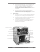
7.2 CIRCUIT SCHEMATIC 2 11 10 12 1 3 7 4 5 ITEM 1 2 3 4 5 6 7 8 9 10 11 12 UGH020/0301 6 9 8 DESCRIPTION Compressor Air cooled condenser Liquid receiver Filter-drier Refrigerant sight glass Expansion valve Evaporator Pump To process connection From process connection Reservoir tank Refrigerant safety switch VL Series Portable Chillers, 0.25 to 1.
THIS PAGE INTENTIONALLY BLANK Page: 32 VL Series Portable Chillers, 0.25 to 1.
8.0 APPENDIX 8.1 8.2 8.3 8.4 8.5 8.6 8.7 8.8 UGH020/0301 SPECIFICATIONS OPERATION BELOW 45°F WATER QUALITY CONTROL INHIBITED PROPYLENE GLYCOL CHILLER CAPACITY AND DERATE CHART PRESSURE - TEMPERATURE CHART FOR R-22 REFRIGERANT ENGINEERING FORMULAS SPARE PARTS LIST VL Series Portable Chillers, 0.25 to 1.
8.1 SPECIFICATIONS VL Air-cooled Portable Chillers: 0.25 to 1.5 tons MODEL VLA-.25 Performance characteristics Capacity* tons 0.25 Compressor Hp {kW}✝ 0.25 {0.19} Pump Hp {kW} 0.25 {0.19} Chilled water flow‡ gpm {lpm} 0.6 {2.3} Chilled water pressure‡ psi {bar} 60 {4.1} Reservoir capacity gal {liters} 4 {15} Dimensions in {mm} Height 33 {838} Width 18 {457} Depth 24 {610} Pipe size NPT in. Process (to and from) 0.
8.2 OPERATION BELOW 48°F A. A chiller typically operates with a setpoint of 50°F or higher. However, if setpoints between 20° - 48°F are required, special precautions must be taken to prevent freezing and possible damage. Attention must be given to freeze protection, water supply and safety adjustments. B. FREEZE PROTECTION 1. It is understood that untreated water freezes at 32°F. Therefore, an inhibited propylene glycol and water solution must be used in lieu of ordinary water.
Therefore, the water supply source must be disconnected and the connection capped. The operator must monitor the water/glycol level and manually make-up to maintain proper reservoir level. D. SAFETY ADJUSTMENTS 1. To ensure safe and efficient operations at lower setpoints, adjustments of the freezestat and low pressurestat factory settings are required. Figure 8.2B lists the appropriate settings. Figure 8.2B E. 2.
8.3 8.4 WATER QUALITY CONTROL A. Lack of, as well as, improper water treatment can damage the chilling unit. The services of a competent water treatment specialist should be obtained and their recommendations followed. It is the equipment owner’s responsibility to prevent damage from foreign material or inadequate water treatment. B. The two main things to consider for water treatment in chillers are corrosion and organism growth. Proper chemical treatment can control PH levels and algae growth.
C. USE OF PLAIN GLYCOL: 1. D. AUTOMOTIVE BASED ANTIFREEZE: 1. E. Even through they do lower the freeze point, plain glycols are even more corrosive than water. The corrosion rate of plain ethylene glycol on iron, for example, is more than 2.5 times faster than plain water. On steel, it is 4.5 times faster. SHOULD NEVER BE USED! Automotive antifreeze contains silicate based inhibitors, which are compatible with automotive components.
8.5 CHILLER CAPACITY AND DERATE CHART Standard chiller rating is at 50°F. For all other temperature settings, output tonnage is altered as follows: OUTPUT FULL TEMPERATURE AVAILABLE % °F CAPACITY 60 105% 50 100% 45 90% 40 80% 35 70% 30 60% 25 50% 20 40% 15 30% * 10 22% * 5 15% * 0 9% * -5 5% * NOTES: If operation of the chiller at less than 48°F is required, an inhibited propylene glycol solution is required. Consult factory for chiller operation below 20°F.
8.6 PRESSURE-TEMPERATURE CHART FOR R-22 REFRIGERANT SATURATED TEMPERATURE FREON PRESSURE 40°F 68 45°F 76 50°F 84 55°F 93 60°F 100 65°F 112 70°F 122 75°F 132 80°F 144 85°F 156 90°F 168 95°F 182 100°F 196 THESE PRESSURE/TEMPERATURE RELATIONSHIPS ARE IN AN AT-REST, SATURATED CONDITION.
8.7 UGH020/0301 USEFUL ENGINEERING FORMULAS VL Series Portable Chillers, 0.25 to 1.
8.
Conair has made the largest investment in customer support in the plastics industry. Our service experts are available to help with any problem you might have installing and operating your equipment. Your Conair sales representative also can help analyze the nature of your problem, assuring that it did not result from misapplication or improper use.
EQUIPMENT GUARANTEE Conair guarantees the machinery and equipment on this order, for a period as defined in the quotation from date of shipment, against defects in material and workmanship under the normal use and service for which it was recommended (except for parts that are typically replaced after normal usage, such as filters, liner plates, etc.). Conair’s guarantee is limited to replacing, at our option, the part or parts determined by us to be defective after examination.