Winpower Software User Manual UPS CUPS650,CUPS850,CUPS1200,CUPS2200 V1.
Table of Contents Chapter 1 Winpower Introduction ............................................................................. 4 1. Quick Installation and Setup for WinPower Software ............................................ 4 2. Winpower profile .................................................................................................. 16 3. Winpower Structure .............................................................................................. 16 4. Winpower Application Range..........
5. How to realize the network shutdown function .................................................... 84 6. How to realize Setting up shutdown parameter .................................................... 85 7. How to realize the modification of Device control parameter .............................. 88 8. How to realize system administrator operation and password modifying realize 89 9. How to realize sending event message by email .................................................. 90 10.
Chapter 1 Winpower Introduction 1. Quick Installation and Setup for WinPower Software A. On the WinPower Installation menu, simply follow on-screen instructions and key in the software serial number. The installation will be automatically proceeded. Enter the Right serial number here!! B. The software will start automatically after the Operation System is started. WinPower appears as a “Green Plug” icon in the right bottom corner of the Traybar. It means the WinPower is running now.
C. If the WinPower is running and you execute the software again then you would see a message for “Minimize” or “Exit”. The message is also shown as below. If you can see it then it means that you already execute the software twice. D. After you start the system and the WinPower is also running in the Traybar, you have to use “Right Click” on the Green Plug then click on “Start the Monitor “to switch on the main screen of the software. Right Click here then click on “ Start Monitor “ E.
F. Here is the main screen of the software. Before you login the software as an administrator, you will see a (Read only) message on the title of the software. It means that you only can monitor the UPS and you cannot change any setting of the software or the UPS. G. To change settings, you need to log in WinPower as an administrator by going to “Act as Administrator” option of System section. The default password is Administrator.
The default password is Administrator 7
H. Now, you can find the information of (Read only) is gone. Hence, you can go access other sheets of the software to have your own setting for the software and the UPS now.
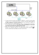
1. To support the remote monitor/control function of WinPower, you need to have the similar connection as above. It means that the Agent is connected to the UPS via RS232/USB and the other Computers are protected via the AC Power only and all the computers are communicated under the same Network with LAN. 2. All the computers need to install the WinPower software to keep them with the same interface for remote shutdown application.
4. If all the computers are communicated within the “same section of network”, the software will detect all the PC which is installed the WinPower and show them in the left window of WinPower as above photo. Notes: “Same section of network” means the three front numbers of its IP address is the same just like 192.168.1.XXX. 5. If the IP address is out of the same section of the Agent, you have to key-in the IP manually for doing the remote monitor/control via “Monitor”->”Monitor Remote Device” 6.
This part is used for the local Agent only. This part is used for the remote PC 7. There are three items will effect the UPS backup time of the local Agent as below. A. Battery Backup Time (AA minutes) B. Begin shutdown immediately while battery low C. System shutdown need time (CC minutes) 7-1. In normal status, when the backup time reaches the value of AA minutes, the WinPower would send the command to shutdown the PC. After the CC minutes, the UPS would also shutdown automatically.
7-3. If you disable the function of item B, once the UPS transfer to battery mode for XX minutes (XX
9-1. Refer to the left setting, it means that the backup time of the UPS in USB is 10 minutes. 9-2. When the UPS of the Agent transfer to battery mode for 2 minutes, the Agent will send out the shutdown command to 192.168.1.2 & 192.168.1.3. 9-3. When the UPS of the Agent transfer to battery mode for 5 minutes, the Agent will send out the shutdown command to 192.168.1.5 9-4 When the UPS of the Agent is going to shutdown (10 minutes on this sample), the Agent will send out the shutdown command to 192.168.1.
11. The new option: Multi-UPS input If there are more than one UPS supplying power to the local agent as below, you want to safely shut down or suspend the local agent before all UPS can’t supply power to the local agent. You should select the “Multi-UPS input” option in the “shutdown settings” dialog of each UPS and set condition, refer to the following picture. The local agent won’t be shut down or in suspend mode until all the condition of all UPS is met.
2. Winpower profile Winpower is a device monitoring software, which supports individual computer and computers connected with network (including LAN & WAN). It is used to monitor the intelligent device to protect computer systems from being shut down abnormally when power fails. User can monitor and configure the device on any computer in the same LAN.
Diagram 1-2-2 4. Winpower Application Range Application of individual computers refers to the following Diagram 1-3-1. Diagram 1-3-1 Application in the LAN refers to the following Diagram 1-3-2. Diagram 1-3-2 Application in the Internet refers to the following Diagram 1-3-3.
Diagram 1-3-3 5. Winpower Functions & Advantages When Agent is started, it will protect your equipment continuously in every moment. Uninstalled easily and clearly with no trace. Never increase the spending of system. You can have a detailed view about all information of the device, such as utility power, device type, load and battery. The information is shown in the same window, so you can take all the information in a glance.
Chapter 2 Winpower Installation, Start & Uninstall 1. System Requirements 128 MB physical memory at least (256MB is recommended) 160 MB hard disk space at least More than 256 colors and 800 * 600 resolutions or above display is recommended The user is required to have the right as system administrator On Linux or UNIX operating system, user must log in system with “root” account to carry out the installation.
Diagram 2-3-1 For Windows platform, enter \Windows directory, run setup.exe to start the installation. Refer to the following diagram 2-3-2-1. Diagram 2-3-2-1 Note: For windows vista, windows 7 and windows 2008, enter \Windows directory, you should run setup.exe as an administrator. Right click on the setup icon, then select “Run as administrator”, a “user account control” dialog will pop up, please select “Allow”. Refer to the following diagram 2-3-2-2.
Diagram 2-3-4 Read the introduction. Refer to the following diagram 2-3-5. Diagram2-3-5 Click “Next” and input the Serial Number, Refer to the following diagram 2-3-6.
Diagram 2-3-6 Click “Next” and choose install folder. Refer to the following diagram 2-3-7. Diagram 2-3-7 Review the Pre-installation Summary. Refer to the following diagram 2-3-8.
Diagram 2-3-8 The installing process, refer to the following diagram 2-3-9. Diagram 2-3-9 When the installation program is completed, click “Done”. Refer to the following diagram 2-3-10.
Diagram 2-3-10 If the software is installed successfully, winpower application can be found in the Start menu\Programs\. Refer to the following diagram 2-3-11. Diagram 2-3-11 For console mode: 1. Enter the directory according the system, run setup.bin or setup_console.bin to start the installation program. Note: For UnixWare platform, make sure JRE has been installed in your system, then enter the /GenericUnix directory to start the setup. 2.
Diagram 2-4-1 The Agent can be start by the following methods: 1) Run the Winpower from Start\Program\Winpower will start the TrayIcon and Agent. Refer to diagram 2-4-1. 2) Right click the agent icon shown on the bottom right corner of the display and select the “Start Agent” item. Refer to Diagram 2-4-2. Diagram 2-4-2 3) On all Windows operating system, agent can be started automatically when the computer reboots.
Set Agent to be auto started when System boots: Open “System Preferences -> Accounts -> Login items”; click “+” icon to add the “Applications/Winpower/Agent” as Login auto start item. Refer to the following diagram 2-4-5. Diagram 2-4-5 Start Agent: You can double click the agent link in "Applications/Winpower" directory to start the Agent. You can also start it in terminal by enter install directory and execute command: Enter “/opt/MonitorSoftware” directory and execute command: sudo .
5. Uninstall Winpower On Windows operating system There are two methods of uninstalling Winpower One is to click “Uninstall Winpower” icon in “Start/Program/Winpower” with left mouse button, refer to Diagram 2-5-1 as below. Diagram 2-5-1 Note: On Windows Vista, Windows 2008 and Windows 7, make sure you have administrator privilege, right click and select “Run as administrator”. The other is to left click “Control Panel/”Add/Remove Program”/Change/Remove(C)” button, refer to Diagram 2-5-2 as below.
Diagram 2-5-3 Click the “Uninstall” to begin to uninstall Winpower software, refer to the following diagram 2-5-4. Diagram 2-5-4 Click “Done” and Winpower has been uninstalled completely. Refer to the following diagram 2-5-5.
Diagram 2-5-5 On Mac OS X: Open the Terminal from “Applications/Utilities/Terminal”, execute commands: cd /opt/MoniorSoftware sudo ./Uninstall Input the system account password when it prompts, and uninstall will be carried out with administrator privilege. The software can be uninstalled completely. If you only execute the command”./Uninstall”, maybe some files of the software can’t be uninstalled. On Linux and UNIX: Open the Terminal, enter "/opt/MonitorSoftware" directory and execute command:.
Chapter 3 Winpower User Interface 1. "Winpower Manager" window Winpower Monitor shows "Winpower Manager" window, which displays a list of agents within the LAN. There is a tree view on the left side of the window, which displays a hierarchical list of items. Such as “Root”, “networks”, the Agent, the COM port, USB port and the UPS or ATS models or telecom power. By clicking an item for UPS, the user can expand or collapse the associated list of submenu. Refer to the following diagram 3-1-1.
Diagram 3-1-1-1 For ATS, refer to the following diagram 3-1-1-2. Diagram 3-1-1-2 For Inverter system, refer to the following diagram 3-1-1-3.
Diagram 3-1-1-3 If you select one of the UPS model from the List, details about it will be displayed on the right side, Refer to the following diagram 3-1-2-1. 1. The middle area displays the UPS Status Figure. The Status Figure is different according to various UPS status and UPS type. 2. The upper area displays the UPS Status Description and recommendation, and the Agent system times with right align. 3. The lower area displays last two events information. 4.
Diagram 3-1-2-1 Illustration of UPS Status information bar: The UPS status figure contains five parts: AC LINE, UPS, BATTERY,LOAD and BYPASS.
1. The middle area displays the telecom power Status Figure. The Status Figure is different according to telecom power status. If there is something wrong with some module, the related figure will turn red. For example, STS in above figure. Otherwise, it is green or white. 2. The upper area displays the telecom power Status Description. If one or more module of inverter, STS, or rectifier has broken, it will show “inverter/STS/rectifier warning & fault” in red instead of detail warning or fault.
Diagram 3-1-2-4 1. The top area displays the manufacturer and model name of ATS. Sometimes, the manufacturer may not be shown. For example, “ATS” means that the model name is ATS. The bottom area displays the serial number and firmware version of ATS. 2. The middle area displays the ATS Status Figure. There are five lights: S1, S2, SW1, SW2, F1 and three information frames. Also, there are some current lines in black or green. 3. The S1 is black when Input source 1 failed (no power on source).
Diagram 3-2-1-1 Diagram 3-2-1-2 By clicking the item in the tree view, user can get the information following, refer to the diagram 32-1-3. 1) All the computer running Winpower Agent on the LAN. 2) Device COM Port or USB Port. 3) The model type of Device to which the Agent is connecting. 4) The Current Status of the Agent which user selected in the tree view.
Diagram 3-2-1-3 2) “Administrator” Dialog "Administrator" dialog can be opened by clicking “Act as Administrator” in the “System” menu. See the following diagram 3-2-2. Enter the administrator password in the edit box and then click “OK” button. If the password is not correct, the system will pop up a message dialog to prompt users that the user password is not correct. If the password is correct, users can get the administrator access right and set up the Agent.
Diagram 3-2-3 Administrator password only can be set by super user in local machine. If you are not a super user yet, the "Administrator" Dialog will pop up first for you to log on as an administrator. User needs to enter a new password in the "New Password" text box and reenter the new password in the "Confirm Password" text box. If the passwords are not consistent with each other, a message dialog will pop up to notify the user that the password is not correct and request the user to enter it once again.
User can click "Purge All" button to delete all of the events. Note: If “Delete” and "Purge All" button are invalid, it means your access right to the current Agent is “Read Only”, you can’t carry out the operation. You should log in as a super user. 5) "Data log Viewer" Dialog "Data Log Viewer" Dialog will pop up when user selects "Data Log" item of "Logs" Menu , or click buttons from toolbar or click “View log” button of data log in the “Record Setting” dialog.
Diagram 3-2-6-1 The default value of the maximum file length of Event Log Viewer is 32KB (the maximum value is 1MB).
Diagram 3-2-6-3 Click the “Settings” button of the event log in the “Record Setting” dialog (Refer to the following diagram 3-2-6-4) to pop up the “Event Action” dialog. Refer to the following diagram 3-2-6-5.
Diagram 3-2-6-5 The default value of the “Maximum file length” in the “Data Log Viewer” is 32KB (the maximum is 1MB). The default value of record interval in the “Data Log Viewer” is 60 second (the maximum is 3600 second). Click the “View Log” button of data log in the “Record Setting” dialog (refer to the following diagram 3-3-5-6) to pop up the “Data Log Viewer” dialog (refer to the following diagram 3-2-6-7).
Diagram 3-2-6-7 Note: Click “Default” button and the parameters in this page will become default. If the “OK” button is invalid, it means your access right to the current Agent is “Read Only”, and you cannot setup the parameters. You should log in as a super user. 7) "Device Control Parameters" Dialog The "Device Control Parameters" Dialog will pop up when user selects "Device Control Parameters" item of “Device” menu. For ON-LINE Device, refer to the following diagram 3-2-7-1.
Diagram 3-2-7-1 For regular LINE-INT UPS, user can enable/disable battery mode alarm audible though this dialog. Refer to the following diagram 3-2-7-2: Diagram 3-2-7-2 For special LINE-INT UPS, Refer to the following diagram 3-2-7-3.
Diagram 3-2-7-3 Refer to the following table 3-2-7-3.
Diagram 3-2-7-4 For ATS, Refer to the following diagram 3-2-7-5 46
Diagram 3-2-7-5 Refer to the following table 3-2-7-5. Parameter Buzzer Status Preferred Source Synchronization Value Delay Transfer Time on Asynchronous Input Voltage Acceptable Range Input Frequency Acceptable Range Nominal Voltage Value can be Enable, Mute, Disable 1 - The Preferred source is S1 2 - The Preferred source is S2 The value can be 10,15, or 20.
8) "Event Action" Dialog The “Event Action” dialog can be opened, by clicking “Event Action” item of “Device” menu or button in the toolbar. Refer to the following diagram 3-2-8. In the “Event Action” dialog, users can select that which action will be carried out when some events occur. For each event, the actions that users can select are Record, Broadcast, Email, Send SMS and Send Pager.
Diagram 3-2-9 The function is only for UPS. In the “Shutdown Settings” dialog, the setting parameters are shown in the following Table 3-2-9.
Shut down UPS __ __ __ yes Hibernate System __ __ __ No Multi-UPS input __ __ __ NO System shutdown need time Minute 99 1 2 Remote Shutdown by Agent XX min shutdown system __ __ __ No Minute 4320 0 0 Run Command File before Shutdown __ __ __ Nothing Shutdown File Max Execution Time Begin Shutting down immediately while battery low Minute 60 1 1 __ __ __ Yes Shut down when remaining battery time is below Minute 1440 1 2 50 off.
Shutdown remote Agents' Conditions Agents be Shutdown __ __ __ __ __ __ __ __ Shutdown Alarm Interval Start Warning before Scheduled Shutdown Minute 60 1 1 Minute 60 1 10 UPS when the actual remaining time is blow the setting value. The condition can be "UPS be shutdown" or "The time on battery exceeds setting time". When shutdown condition is satisfied, Agent will send shutdown signal to the appointed remote Agents. The interval that Agent pop up an alarm message before shutting down.
Diagram 3-2-11 The function is only for UPS. The function can be used to display and setup UPS self-test task. UPS self-test task has two types: “once” and “monthly”. UPS self-test type: UPS self-test for 10 seconds, UPS self-test to battery low, and UPS self-test for the appointed time. The appointed time range is 1 to 99 minutes, and the default value is 10 minutes. The “UPS Test Manager” dialog contains two parts: task list and calendar.
Diagram 3-2-12 The function is only for UPS. The “UPS On/Off Manager” dialog is used to display and set up UPS On/Off tasks. The UPS On/Off tasks include two types: “Once” and “Weekly”. The UPS Power Off time range (from shutdown to turning on next time) that can be set is 1-9999 minutes, i.e. the longest power off time is 6 days 22 hours and 39 minutes. The input range for the year is 2002-2035. The “UPS On/Off Manager” dialog contains task list and calendar.
Diagram 3-2-13 The function is only for UPS. The “Schedule Viewer” dialog is used to show the set up UPS Power On/Off and self-test tasks. “Schedule” dialog contains task list and calendar graphic. Only the tasks of the current month are displayed in the task list. We use red dot to denote the Power Off action, green dot to denote the Power On action and blue dot to denote the self-test action in the calendar.
Diagram 3-2-14 The "Broadcast To" list box lists the users. The user item must be selected if the user wants to receive broadcast message. You can add and delete user item by click "Add" and "Remove" button (Note: the "All Users" and "Domain User" item can’t be deleted). "All Users" means all computers in LAN. "Domain User" means computers in the same domain with local Agent.
Diagram 3-2-15 The included items of the email parameter setting are shown in the following Table 3-2-15. SMTP Server Name SMTP Account Name Password Port Encryption This is the mail server, which is used to send emails to the appointed users. It could accept two formats: IP address and host name. For example: smtp.163.com This is the account for logging in the server. Enter the complete address format here. For example: yyy@163.
The “Receiver E-Mail Address” list box lists the email addresses. Click "Add" button to add an email address item. Select an address item and click "Remove" button will delete the item. Selected an email address item, and click the "Test" button will send a test email to the email address. The "UPS message", “Telecom Power System message” and “ATS message list” list boxes list all the message, you can select the message by click the check box with the message item.
Below is the use remark of SMS setting: 1. Sender SMS is sent through GSM modem or mobile phone connected with your computer. User should select COM port that is being used by GSM Modem or mobile phone, and set baud rate of the COM port. Locus means that where user is. 2. Receiver: Receiver is the mobile phones numbers who can receive the SMS. It can be one or more. If the Event that you have selected occurs, winpower will send the event message to the phone numbers in the "Receiver" list. 3.
Diagram 3-2-17-2 18) Bottom image If you select the submenu “BottomImage” of the menu “Preference”, you can change the bottom image of the interface. Refer to the following diagram 3-2-18.
Diagram 3-2-18 19) Temp The centigrade or Fahrenheit temperature shown in the interface can be changed by selecting the submenu “Temp” of the menu “Preference”. Refer to the following diagram 3-2-19. Diagram 3-2-19 20) Date Format The date format can be changed by selecting the submenu “DateFormat” of the menu “Preference”. The format is “Year/Month/Day”, “Month/Day/Year” or “Day/Month/Year”. Refer to the following diagram 3-2-20.
Diagram 3-2-20 21) Advance Settings The font, size, color and bottom image of the interface can be changed by selecting the submenu “Advance Settings” of the menu “Preference”. The “Advance Settings” dialog contains two parts: “General” and “BottomImage”. Refer to the following diagram 3-2-21-1.
Diagram 3-2-21-1 Note: If you click “Default” button, the parameters in this view will be turned into default value. If the “OK” button is invalid, it means that your access right to the current Agent is “read only”, so you can’t carry out the parameter setup. You should log in as a super user. In the “BottomImage” view: If you click “None” box, the bottom image of the interface is “background color”. Users can select the color that they want by clicking “Color” box.
Diagram 3-2-21-2 Note: Click “Default” button, the parameters in this view will turn to default value. If the “OK” button is invalid, it means that your access right to the current Agent is “read only”, and you can’t carry out the parameter setup. You should log in as a super user.
Diagram 3-2-22 23) "Communication Port Settings" Dialog The "Communication Port Settings" dialog can be opened from the "COM Port Setting" item of "System" menu. On Linux and UNIX, Winpower can't detect the serial port devices automatically. If the system has a Serial Port that can’t be found in the default setting table, you must add it manually in the "Communication Port Settings" dialog. Refer to the following diagram 3-2-23.
Note: If the "OK" button is invalid, it means that your access right to the current Agent is “read only”, so you can’t carry out the parameter setting. You should log in as a super user. 24) "SNMP" Menu The SNMP menu has nine menu items: Menu Item Description Search Device Search Device window - search for devices monitored by SNMP cards. Modify Device Modify Device window - modify the device information. Delete Device Select this item to delete the appointed SNMP device.
25) "Search Device" Dialog Note: If the Search button is disabled, the current Agent is read-only, and you cannot set up the parameters. Select “Act as Administrator” from the “System” menu to log in as super user. To add devices: 1. Click the “Search Device” item from the” SNMP” menu. 2. Select which TCP/IP protocol that SNMP support in the Search Device dialog, protocol IPv4 or IPv6. For IPv4, both single device and segment device searches are supported.
Diagram 3-2-26 Note: If the OK button is disabled, the current Agent is read-only, and you cannot set up the parameters. Select “Act as Administrator” from the “System” menu to log in as a Super user. 27) "Add Area" Dialog To open the Add Area window, select “Add Area” from the “SNMP” menu. You can add areas and relative information. The new areas are displayed below the SNMP node in the left tree view. Refer to the following diagram 3-2-27.
29) "SNMP Trap Receiving Port Setting" Dialog To open the SNMP Port Setting window, select “SNMP Trap Receiving Port Setting” from the “SNMP” menu. You can change the SNMP Port if the default Port 162 is occupied by other programs. The range of the new SNMP Port is 1 to 65535. Refer to the following diagram 3-2-29. Diagram 3-2-29 Note: You must select the SNMP node at the left tree view. If the OK button is disabled, the current Agent is read only, and you cannot perform this task.
Diagram 3-2-30 Note: To carry on this operation, you must have administrator privilege. Select “Act as Administrator” from the “System” menu to log in as a Super user. 31) "Event Log Setting" Dialog Note: If the OK button is disabled, the current Agent is read-only, and you cannot set up the parameters. Select “Act as Administrator” from the “System” menu to log in as a Super user. 1.
32) "Load segment control" Dialog Note: the function is only for some UPS that support load segment setting. User can open “Load Segment Control” dialog by select “Load Segment Control” from the “Device” menu. User can set manual shutdown or startup load segment. And also can set the shutdown and startup timer value.
Chapter 4 How to do 1. How to realize the conversion of the appointed COM port If the computer with Winpower has multiple serial ports, Winpower can allow the users to change the current serial ports connected to the device via “Auto search Device” menu. Refer to the following Diagram 4-1-1. Diagram 4-1-1 There is a tree view on the left displaying a hierarchical list, such as Root, LAN, the Agent name, the COM port and the Device model. Refer to the following diagram 4-1-2.
Diagram 4-1-2 When user selects a device model, "Manager" Window will show detail about the device on the right. For Linux and UNIX, Winpower can't detect the serial port device automatically. If the serial port can’t be found in the default setting table, you must add it manually in the "Communication Port Settings" dialog. Refer to the following Diagram 4-1-3. Diagram 4-1-3 The default serial port devices setting: refer to the following Table4-1-1.
Tru64 FreeBSD /dev/tty00 /dev/tty01 /dev/ttyd0 /dev/ttyd1 Table4-1-1 Note: For the first time, starting Agent takes more time than later to communicate with the device. And the software will keep a record of the device. Next time, Winpower will start according to the last record. If device COM port, device model or slave address have been changed, user should click "Auto Search Device" item of "System" menu to get correct device information. 2.
All users indicate that the message will be sent to all computers in the same network with this computer, no matter whether it is in the same domain. Domain users indicate that the message will be sent to all computers only in the same NT domain with this computer. Special users indicate that the message will be sent only to one or a group of defined users, but not others any more. To realize the function, you should set up the “Add Broadcast User” dialog first. Refer to the following diagram 4-2-2.
Diagram 4-2-3 Note: Only on Windows, the function can be carried out. To receive broadcast message, "Winpopup" in Windows95/98 and "Messenger Service" in Windows NT/2000 must be started. 3. How to realize the schedule of adding/Removing UPS self-test Click the “Battery Self-Test Schedule” menu of “Device” menu to popup the “UPS Test Manager” dialog. Refer to the following diagram 4-3-1.
Diagram 4-3-1 Note: If the “OK” button of the dialog is invalid, it means that your access to the current Agent is “read only”, and you can’t setup it. You should log in as a super user. Add the task of UPS self-test Click the “Add test” button, and will pop up the “UPS Self-test” dialog. Refer to the following diagram 4-3-2.
Diagram 4-3-2 In the dialog, users can make a choice of setting UPS self-test task as in a special time or monthly from the options of “once” or “monthly”. You may set the start time of UPS self-test in date and time combo box. Note: the new self-test task can’t conflict with the UPS self-test or UPS Power on/off task that has already been set. You can select one of the self-test modes from the following.
Diagram 4-3-3 Press the “OK” button to finish the setting. Refer to the diagram 4-3-3. Modifying UPS self-test task Select one of the UPS self-test tasks in the task list, click “Modify” button to modify the task that has been set in the popup dialog. Refer to the following diagram 4-3-4.
Diagram 4-3-4 After finishing the modification, click “OK” button to save. Remove UPS self-test task Select one of the UPS self-test tasks in the task list. Click “Remove” button to cancel the task. Refer to the following diagram 4-3-5.
Diagram 4-3-5 4. How to realize the schedule of adding/Removing UPS on/off Click the “UPS On/Off Manager” menu of the “Control” menu, and will pop up the “UPS On/Off Manager” dialog. Refer to the following diagram 4-4-1.
Note: the function only for UPS. If the “OK” button of the dialog is invalid, it means that your access to the current Agent is “read only”, and you can’t modify it. You should log in as a super user. Add the task of UPS On/Off Click “Add UPS On/Off” button, and will pop up “Off UPS” dialog. Refer to the following diagram 44-2. Diagram 4-4-2 In the dialog, users can make a choice in the setting of UPS Power On/Off weekly or in a special time via the option of “Once” or “Weekly” in the combo box.
Diagram 4-4-3 Click the “OK” button to finish the settings. Refer to the following diagram 4-4-3. Modify the task of UPS On/Off Select one of the UPS On/Off tasks in the task list, click “Modify” button to modify the tasks that have been set in the popped up dialog. Refer to the following diagram 4-4-4.
Diagram 4-4-4 After finish the modification, press the “OK” button to save. Remove the UPS On/Off task Select one of the UPS On/Off tasks in the task list, click “Remove” button to remove the task. Refer to the following diagram 4-4-5.
Diagram 4-4-5 5. How to realize the network shutdown function The function is only for UPS. Click the “Shutdown Parameter” item of the “Device” menu, and will pop up “Shutdown Settings” dialog. Refer to the following diagram 4-5-1.
Diagram 4-5-1 Accept remote Shutdown signal from other Agent: Click the “Add” button in the ”Shutdown Options”, enter IP address of agent in the popped up dialog, and click the “OK” button to finish the setting. When the Agent received the specified agent's shutdown signal, system will be shut down in delay time.
Diagram 4-6-1 Click the “Add” button in the “Shutdown Options”, and enter the IP address or host name of agent in the popped up “Agent’s IP address” dialog. Refer to the following diagram 4-6-2. Diagram 4-6-2 Click the “Add” button in the “Shutdown Remote Agents”, and configure the Shutdown conditions in the popped up “Shutdown Remote Agents” dialog.
Diagram 4-6-3 Configure the shutdown parameter in the dialog: Shutdown options: Battery backup time: The time that the UPS's battery is able to supply power when utility power fails. Begin Shutdown Immediately when Battery Low: When the check box is selected and battery low event occurs, Agent will shut down the UPS immediately, otherwise the shutting down time will be controlled according to battery backup time.
down. Start Warning before Scheduled Shutdown: If user has setup shutting down on schedule, agent will begin to alarm user before the set time. 7. How to realize the modification of Device control parameter For ON-LINE UPS: Click “UPS control parameters” item of the “Device” menu, and will pop up “UPS control parameters” dialog. Refer to the following diagram 4-7-1.
this time the “ON” button on the UPS panel can’t turn on the audible alarm of battery supply. Work On Bypass When UPS Turned Off: to choose “Yes”, when UPS is not turned on, it is in the mode of bypass supply. To choose “No”, when UPS is not turned on, no bypass output is offered.
If the password is incorrect, warning message will popup. Refer to the following diagram 4-8-2. Diagram 4-8-2 Modifying the system administrator password Click the “Modify Administrator Password” menu of the “System” menu to popup the “Administrator Password Settings” dialog. The menu is valid within the local Agent only. Refer to the following diagram 4-8-3. Diagram 4-8-3 Enter the new password in the “New Password” edit box, reenter it in the “confirm password” edit box.
Diagram 4-9-1 SMTP Server is the SMTP Server’s address; SMTP User is the account for logging in the server; If SMTP mail server needs password, authentication user should input the password; Port is for SMTP service, user should set the right port; Encryption is for selecting encryption mode depending on SMTP server. Set the receiver Email Address: click the “Add” button of the “Email Settings” dialog, and then pop up “Add Receiver E-mail Address” dialog. Refer to the following diagram 4-9-2.
Diagram 4-9-2 Enter the Email Address in the “Add Receiver Email Address” dialog, and select “OK” button to save and exit. Completing event setting: select one of the events (For example, UPS battery low) from the “Send message”; and then select the user that has been set in the “Receiver Email Address” list, finally select the “OK” button to save and exit. 10.
Diagram 4-10-1 Below is the use remark of SMS Setting, refer to the diagram 4-10-1. 1. Sender: SMS is sent through GSM modem or mobile phone connected with your computer. User should select COM port used by GSM Modem or mobile phone, and set baud Rate of this COM port. 2. Receiver: the mobile phones numbers that can receive the SMS. It can be one or more. If the event occurs, the software will send the short message to all the phone numbers in the "Receiver" list. 3.
Diagram 4-11-2 Startup Monitor: Refer to the following diagram 4-11-3. Diagram 4-11-3 Select the Device you want to monitor You can select the Device from the tree view on the left side of the window.
If the Remote Accept Control Permission Switch of the Agent is not on, you can only monitor but not control. The submenu “Act as Administrator” of the menu “System” is gray and can’t be selected. So if you don’t log in as an administrator, you can’t control all of the operation, Refer to the following diagram 4-11-4. Diagram 4-11-4 If the Remote Control Permission Switch of the Agent is on, you can monitor and control this device.
Diagram 4-11-5 12. How to realize remote control of any device in different network in LAN Precondition The computers with Winpower must setup TCP/IP protocol in the communication protocol. Steps for realization Keep the communication smooth: test with network command “PING” under command prompt window. For example, a computer named tj2k with IP address 192.168.2.228, you can test with command “ping 192.168.2.228”.
Remote Control Permission Switch: This is a selectable menu item. User can click the submenu “Accept Remote Device” of the “Monitor” menu. Refer to the following diagram 4-12-2. Diagram 4-12-2 Select the device you want to monitor Click the “Monitor Remote Device” item of the “Monitor” menu, and will pop up the “Monitor Remote Device” dialog. Refer to the following diagram 4-12-3. Diagram 4-12-3 User can enter a computer name or IP address in the "Monitor Remote Device" Dialog.
Diagram 4-12-4 If the Remote Control Permission switch of this Agent is not on, then you can only monitor but not control. Refer to the following diagram 4-12-5.
If the Remote Control Permission Switch is on, then you can monitor and control this device. So after you login as a super user, you can control all of the operation, Refer to the following diagram 412-6. Diagram 4-12-6 13. How to realize the Remote Control of any one of the device in Internet Precondition The computers with Winpower must setup TCP/IP protocol in the communication protocol. The computer with Winpower has been connected to the Internet.
Diagram 4-13-1 Remote Control Permission Switch: This is a selectable menu item. User can open the submenu “Accept Remote Device” of the “Monitor” menu. Refer to the following diagram 4-13-2. Diagram 4-13-2 Select the device you want to monitor Click the “Monitor Remote device” item of the “Monitor” menu, and will pop up the “Monitor Remote Device” dialog. Refer to the following diagram 4-13-3.
Diagram 4-13-3 User can enter a computer name or IP address in the pop-up "Monitor Remote Device" dialog. Click the “OK” button to finish the setting. Now you can find the device in the WAN, select the device from the tree view on the left side of the window. Refer to the following diagram 4-13-4. Diagram 4-13-4 If the Remote Control Permission switch of this Agent is not on, then you can only monitor but not control. Refer to the following diagram 4-13-5.
Diagram 4-13-5 If the Remote Control Permission Switch is on, you can monitor and control this device. So after you login in as a super user, you can control all of the operation, Refer to the following diagram 4-136.
14. How to install software on VMware ESX 3.5/4.0/4.1 This section describes the installation and configuration of the Software on a VMware ESX Server. Software allows you to connect VMware ESX 3.5/4.0/4.1 with a UPS through the RS232 or USB port. Please notice: When you want to connect VMware ESX 4.0/4.1 with a UPS through USB port, you should execute the command to activate the usb.o on your System to make the USB communication normal, and then restart the VMware ESX 4.0/4.1 server.
▲ If auto-run is not enabled, run the VMware Tools installer. Click Start > Run and enter D:\setup.exe, where D: is the first virtual CD-ROM drive. 5. Follow the on-screen instructions. ▲ On Microsoft Windows Server 2003, the SVGA driver is installed automatically, and the guest operating system uses it after it reboots. ▲ After you install VMware Tools, Microsoft Windows 2000 and Microsoft Windows XP guest operating systems must be rebooted to use the new driver.
Diagram 4-14-1 Configuration This section explains configuration for the Software and for the VMware server. Software Configuration The VMware server works in console mode and can’t be used for configuration. Use a remote Agent with the same Software version to configure the VMware server. 1. Start the manager interface on the remote software Agent in the Microsoft Windows operating system. 2. If the two Agents are in the same LAN, the VMware server client will be added to the topology automatically.
Diagram 4-14-2 VMware Server Configuration All hardware elements must have an operational network configuration that allows them to communicate freely with each other. Software uses TCP and UDP for communication with UPS. 1. Confirm that the following UDP ports are opened on the ESX server Firewall: 2198,2199,2200 2.
3. 4. If you want to disable the firewall permanently, enter the command: chkconfig iptables off To disable the firewall temporarily, enter the command: service iptables stop 15. How to install software on Windows 2008 server core Windows Server 2008 Core OS prepared Before installing software, please ensure the configuration of Windows Server 2008 Core is correct, including network settings, port settings. Note: if you want to set the software by another agent, please shut down the firewall first.
3. Check the status of the processes of UPS monitoring software. Enter command “tasklist” to open the task manager. See below screenshot, if these processes are all running, that means the UPS monitoring software is running normally.
1. Close the interface of the UPS monitoring software and enter the installation path, the default path is c:\Program file (X86)\ MonitorSoftware, enter command: “wpExit” to stop software, waiting for a moment. 2. Enter the installation path, the default path is c:\Program file (X86)\ MonitorSoftware, find the file “UninstallerData”. You can uninstall software in Silent installation method or with Interface uninstall method.
● Select the Open Virtualization Format (OVF) and click Next ● Start VMA, the default user name is vi-admin. Set the password for the first login. VIMA/vMA Shutdown and Startup Configuration NOTE: You can configure the physical machine to boot the automatic operating system on startup. This setting is located in your machine’s basic input/output system (BIOS). For further information, refer to your specific technical hardware documentation.
5. Confirm that the following TCP port is enabled on the VIMA/vMA firewall: 2099 VMware ESXi Server Configuration Note: if the shutdown action is Guest OS shutdown, VMware tools must be installed on each virtual machine. If the shutdown action is Power Off, user is allowed to ignore VMware tools installation. When the shutdown action is Guest OS shutdown, to allow interactions between physical and virtual machines, VMware tools must be installed on each virtual machine. Go to http://www.vmware.
Diagram 4-16-3 5. From within the guest operating system, click OK to confirm that you want to install VMware Tools and launch the Install Shield wizard. ● If auto-run is enabled in the guest operating system (the default setting for Microsoft Windows operating systems), a window opens ● If auto-run is not enabled, run the VMware Tools installer. Click Start > Run and enter D:\setup.exe, where D: is the first virtual CD-ROM drive. 6. Follow the on-screen instructions.
Diagram 4-16-4 2. Insert the VMware server installation CD. Go to \VMware\RPMS to locate the VMware Tools installation package. 3. Log in to the guest operating system from the virtual machine console (see diagram 4-16-5).
Diagram 4-16-5 4. Select the template name and then right-click and select Install/Upgrade VMware Tools from the menu. (see diagram 4-16-3.) 5. Mount the CD with the command: mount /dev/cdrom /mnt 6. Install the package with the command: cd /mnt/VMware/RPMS rpm –Uvh VMware esx*.rpm NOTE: The package name is likely to be different. 7. Configure the VMware Tools with the command: vmware-config-tools.pl 8. Enter number: 1 9.
cd Linux sudo ./setup_console.bin 6. After install software OK, enter software installation file path and execute script “config.pl”: Enter the command: sudo ./config.pl Input the target host ip(or hostname), username, password. Software support multi-hosts shutdown. For example: 172.18.127.125 and 172.18.127.110 will be added, refer to the following diagram: The host information will be saved in hostlist document, refer to the following diagram. Note: The password will be encrypted. 7. Start the Agent.
Diagram 4-16-7 Notice: The shutdown settings dialog of the software agent installed on vMA should be open from the shutdown parameter of device menu, by selecting the agent name on the manager window of another agent installed on operating system with GUI. ● Another software agent should be installed on operating system with GUI, the agent should communicate with UPS by RS232 or USB and should configure shutdown remote agents in shutdown settings dialog.
Diagram 4-16-8 Notice: Another software agent installed on operating system with GUI should be the same version as the software installed on vMA. 17. How to configure the computer powered by Multi-UPS shut down safely For local computer: If there are more than one UPS supplying power to the local computer with software as below 4-17-1, you want to safely shut down or suspend the local computer before all UPS can’t supply power to the local computer.
Diagram 4-17-1 118
Diagram 4-17-2 For remote computer without communication with UPS: If there are more than one UPS supplying power to the remote computer with software, you want to safely shut down or suspend the remote computer before all UPS can’t supply power to the remote computer.
Diagram 4-17-4 120
Diagram 4-17-5 121
Appendix A—Glossary Explanation Agent—Agent is a background application of the Windows/Unix/Linux operating system. UPS Battery Low—When Utility Power fails and battery supplies power, if the battery voltage is lower than a certain value (refer to UPS Specification); UPS will send a warning tone at intervals of 1 second for battery low.
Appendix B---Winpower Event Table Serial Number Event Description 1 2 UPS Battery Low UPS Battery Time Exhaust 3 UPS Fail 4 UPS Output Overload Type of Message Serious Serious Serious Serious Warning 6 Communication Lost 7 AC Fail On Bypass 9 Bypass without output 10 11 12 13 14 15 16 17 18 19 20 21 22 23 24 25 26 27 Output load is more than 110% The connection of communication cable is not good, or communication port fault.
28 29 30 31 32 33 Information Special date Self-test Start Special date Self-test Information Cancel Information Special date Self-test End Information Monthly Self-test Start Information Monthly Self-test Cancel Information Monthly Self-test End 124 . . . . . .
Frequently Asked Questions Question: UPS can’t communicate with Winpower under Debian Etch Stable Core 2.6 18-5-486 Method to fix it: 1. Here are the procedures to solve this question: Login in Debian as root, the permission of general user is limited to install winpower. Debian refuse to login as root, some special settings is needed. Remark a. In the login interface, there are three icons: “Language“, “Session“, “Action“, choose “Action“ b.
Method to fix it: Change the setting of the terminal as the following steps: 1. Click “Terminal” shown on the left corner of Mac 10.5 OS, and select “Preferences…”, There will be a dialog shown as below. Please select “Nerver” of “Prompt before closing” in the “Shell” interface.