CENTURION ® 52CNT4E-ES/CF52374-L-ES 52CNT4E-ES-PD-004/ CF52374-L-ES-PD-004 Owners Manual and Installation Instructions A Continuing Commitment to Excellence
READ AND SAVE THESE INSTRUCTIONS Before beginning installation of your new Concord ® ceiling fan, read and follow these safety precautions. If you are not familiar with national and local electrical codes and basic electrical wiring procedures, we recommend that you have a qualified electrician install your new ceiling fan. Before you begin, TURN OFF THE ELECTRICITY. Determine which circuit your new fan will be using and remove the fuse or turn off the circuit breaker at the main electrical panel.
This ceiling fan was not designed for installation in any location where re it might be exposed to moisture or high humidity. Installation in this type of location could be UNSAFE, will most likely damage the fan and its finish... and will VOID YOUR WARRANTY. Every effort has been made to provide you with proper instructions for the safe installation of this ceiling fan. You could however, encounter situations or problems not covered in this manual.
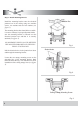
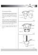
Step tep 1 Install Mounting Brack Bracket Install the mounting bracket onto the electrical junction box in the ceiling using two machine screws, two washers and two lock washers (see figure 1). Junction Box The mounting bracket has slotted holes to enable it to move sideways for proper alignment. Make sure the mounting bracket is centered over the electrical junction box and that it is securely attached (see figure 2). NO MOVEMENT SHOULD OCCUR BETWEEN THE MOUNTING BRACKET AND THE ELECTRICAL JUNCTION BOX.
Mounting Bracket Step 2 Hanging the Fan Body Notice the half ball on the end of the support rod is grooved down one side (see figure 4). This Keyway fits over the small keyway pin on the inside of the mounting bracket and keeps the ceiling fan from spinning on the mounting bracket. Keyway Pin Ball Hanger Support Rod Using your step ladder, lift the fan and place the half ball in the center of the mounting bracket with the keyway pin inserted into the keyway on the ball.
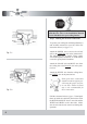
If you are going to use an PD-004 Control Unit with this fan, refer to the Installation Manual for the PD-004 before proceeding further. Green Black Blue White Step 3 Making the electrical connections To operate your ceiling fan with the pull chain(s) and switches mounted on your fan, follow the instruction below (see figure 7-1) Attach the GREEN wire (connected to the half ball) to the GROUND wire in the junction box. The GROUND wire is usually a bare copper wire without plastic insulation.
Step 4 Fan Assembly Support Rod Safety Pin Coupler Cover Yoke Screws Top Plate Remove three screws from yoke cover and lift yoke cover set aside, remove three screws from top plate located on the motor yoke. Lift top plate and set aside. Time Saver:Washers for blade screws can be set on each blade screw prior to installing blades. Locate 13pcs blade attchment screws and washers in hardware pack. Slide blade through center band and align holes. Insert 3pcs blade screws and washers with fingers.
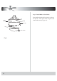
Step 5 Install Bulb & Glass Shade Place bulb included with fan into the socket on the light kit. Place glass shade on light kit and rotate until secure (see figure 9). Center Band Light Kit Bulb Glass Shade Fig.
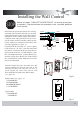
Installing the Wall Control Before you begin, TURN OFF THE ELECTRICITY (at the main circuit panel or fuse box). If you feel unsure of this procedure, have a qualified electrician install this unit. AC IN BLACK TO LIGHT AC POWER INPUT GREEN BLUE GROUND BLACK TO FAN BLACK Disconnect the power and remove the existing wall plate and switch.Set all knobs on the dual slide wall-mounted control in the OFF position.
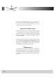
Your new CONCORD ceiling fan is now ready for use. Reset your circuit breaker and restore power to the circuit. See the Operation Instructions below to review the function of each control on your fan. Operation Instructions The pull chain located on the switch housing (see figure 15) controls the speed of your fan. When the fan is OFF, pull the chain once for HIGH speed, twice for MEDIUM speed, three times for LOW speed and fourth time to turn it off again.
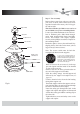
Mounting Bracket Support Rod Retaning Clip and Washer Safety Pin Canopy Coupler Cover Yoke Screws Top Plate Blade screws and Washers Reverse Switch Center Band Light Switch (pull chain) Three Speed Switch (pull chain) Bulb Glass Shade 11
ATTENTION Under the Energy Policy Act of 2005, federal regulations require all ceiling fans with light kits manufactured or imported after January 1, 2009, to limit the total wattage consumed by the light kit to 190 watts. Therefore, this product is equipped with a 190W limiting device. If lamping exceeds 190 watts, the light kit will shut off automatically until the proper wattage of bulbs are installed.