
Instructions / Assembly
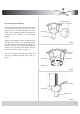

If you are using an extended support rod,
(longer than the one supplied with your fan)
remove the half ball from the support assem-
bly and attach it to the extended support rod
at this point. Make sure to retighten the set
screw and insert the safety pin.
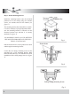
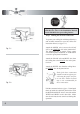
Back off (loosen) the set screws (2) in the sup-
port rod coupler until the inside of the channel
is clear of the screw tip.
Remove and save the safety pin and washer on
the end of the support rod assembly.
Feed the electrical wires from the fan housing
through the support rod.
Thread the support rod into the support rod cou-
pler until the safety pin can be inserted through
the hole in both the rod and coupler.
Tighten both set screws and safety screw on the
support rod coupler.
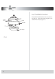
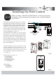
Step 4 Fan Assembly
Slide the ceiling canopy onto the support rod,
followed by the support
rod
coupler cover
Insert the safety pin through the hole in the
support rod coupler and support rod then attach
washer into safety pin and
the retaining clip on
the other side.
7
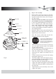
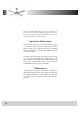
Remove three screws from yoke cover and lift
yoke cover set aside, remove three screws from
top plate located on the motor yoke. Lift top pl-
Time Saver:Washers for blade screws can be set
on each blade screw prior to installing blades.
securely with a phillips screwdriver. Repeat for
the remaining blades.
Reattach to plate to motor yoke and install it by
aligning the key slot holes on the motor yoke us
ing previously removed screws.
Locate 13pcs blade attchment screws and was-
hers in hardware pack. Slide blade through
center band and align holes. Insert 3pcs blade
ate and set aside.
screws and washers with fingers. Tighten
Note: The reverse switch must be site in the
rectangle hole labeled on the top plate.
Blade screws
and Washers
Yoke Screws
Fan Blade
Coupler Cover
Support Rod
Safety Pin
Fig. 8
(see
Top Plate
Center Band
figure 8).