Nautika ® ™ 44NA/52NA 14.553 LBS/18.963 LBS Owners Manual and Installation Instructions Part Number: NA-1220 (Revised 03.25.
READ AND SAVE THESE INSTRUCTIONS Before beginning installation of your new Concord® ceiling fan, read and follow these safety precautions. If you are not familiar with national and local electrical codes and basic electrical wiring procedures, we recommend that you have a qualified electrician install your new ceiling fan. Before you begin, TURN OFF THE ELECTRICITY. Determine which circuit your new fan will be using and remove the fuse or turn off the circuit breaker at the main electrical panel.
This ceiling fan was designed for installation in locations where it might be exposed to moisture or high humidity. This unit meets or exceeds the U.L. requirements for installation in a WET location. Every effort has been made to provide you with proper instructions for the safe installation of this ceiling fan. You could however, encounter situations or problems not covered in this manual.
SOME STARTING TIPS Your first TIP is...READ THESE INSTRUCTIONS. Choose a location to install your new ceiling fan with at least the minimum clearances listed on page 2, paragraph 6. The best performance from your fan can be expected by placing it in the center of the room or structure and out of DIRECT contact with water. If you are unsure or have any doubt about your knowledge of electricity, HIRE AN ELECTRICIAN to install your new fan.
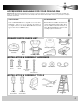
ACCESSORIES AVAILABLE FOR YOUR CEILING FAN Concord® and its Dealer offer numerous accessories for your new ceiling fan. These accessories will add to the versatility and beauty of your ceiling fan. Listed below are some examples with stock number and description. Please see your dealer for complete information and selection. LIGHT FIXTURE EXTENSION RODS Your new Concord® Fan is adaptable to be used with a light fixture. The process is easy and takes only minutes to accomplish.
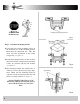
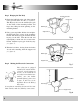
Have you TURNED OFF the Electricity? Ceiling Canopy Mounting Screw Fig. 1 Junction Box Step 1 Attach the mounting bracket Loosen the two canopy mounting screws on the downside face of the mounting bracket. Back them out about half way. This will allow for easier installation of the ceiling canopy later (see figure 1). Install the mounting bracket on the electrical junction box in the ceiling using two machine screws, two washers and two lock washers (see figure 2).
Pull the electric wires in the junction box down through the mounting bracket and then bend them up and back out of the way. This will leave the mounting bracket open and ready to receive the ceiling fan (see figure 4). If you are using an extended support rod, (longer than the one supplied with your fan) remove the half ball from the small support rod that came with the fan and put it on the extended support rod. Make sure to retighten the set screw and insert the safety screw. Fig.
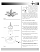
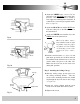
Step 3 Hanging the Fan Body Mounting Bracket Notice the half ball on the end of the support rod is grooved down one side (see figure 6). This Keyway fits over the small keyway pin on the inside of the mounting bracket and keeps the ceiling fan from spinning on the mounting bracket. Using your step ladder, lift the fan and place the half ball in the center of the mounting bracket with the keyway pin inserted into the keyway on the ball.
Attach the GREEN wire (connected to the half ball) to the GROUND wire in the junction box. The GROUND wire is usually a bare copper wire without plastic insulation. It could also be covered in green plastic insulation (see figure 9). Green Black Blue White Attach the BLACK wire and the BLUE wire from the ceiling fan to the BLACK wire in the junction box. Attach the WHITE wire from the fan to the WHITE wire in the junction box. Fig.
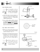
Screw Pads Step 6 Fan Blade Assembly Screw Pads The ABS blades on this unit have a support ridge running down the center of the blade. This ridge should be facing the ceiling after installation. Attach each fan blade to a blade arm with three (3) 3/16” x 1/2” washer head screws and three (3) 3/16” screw pads (see figure 12). DO NOT OVER TIGHTEN THESE SCREWS. Blade Arm Fig. 12 Screws should be tightened until the screw pads are compressed by the screw head.
Fan controlled with wall switch and Light controlled at fan Optional Wiring Diagrams Figure 15 illustrates the wiring used to control the fan with a wall switch plus an optional light fixture controlled at the fixture. Figure 16 illustrates the wiring used to control fan with the pull chain on the electrical switch housing plus an optional light fixture with a wall switch. Fig. 15 Fan controlled at fan with Light controlled at wall switch Fig.
Junction Box Washer Mounting Bracket Screws & Washers Hanger Ball & Support Rod Canopy Canopy Screws Rubber Canopy Retaining Clip Support Rod Coupler Safety Pin Motor Housing Set Screw Switch Housing 3 Speed Switch Light Switch Reverse Switch Fan Blade Screw Washer Fan Blade Blade Holder Arm ® © Great 2000 Enterprises, Inc.