
Installation Instructions
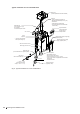

25Mounting and installation work
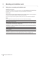
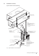
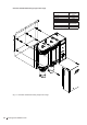
5.2 Installation overviews
Typical installation for duct humidication
Fig. 7: Typical installation for duct humidication
KS10
DS80
DV81
Z261
Humidity sensor or
humidity controller
Return duct
Supply duct
Humidity sensor or
humidity controller
Steam line
– As short as possible (max. length 4 m)
– Adequate upslope/downslope min.15 % (8.5°)
– No restrictions
– Condensate trap at the lowest point
– Hose or xed pipe (with same inner diameter
as steam outlet)
Condsensate line
– Min. downslope 15 % (8.5°)
– No restrictions
– Condensate trap ømin 200 mm
Filter valve or
Shut-off valve and lter 5µm
Water drain connector ø30 mm
Water supply connector G 3/4"
Water supply pipe
(min. inner diameter 8 mm, supplied by others)
1...10 bar / 1...40 °C
(with optional drain water
cooling 2...10 bar / 1...25 °C)
Air proving switch
(external safety chain)
Electrical isolator heating voltage supply
(supplied by others)
Rmin:
300 mm
ømin: 200 mm
ømin: 40 mm
Electrical isolator control voltage
supply (supplied by others)
Drain hose (supplied)
– internal diameter ø30 mm
– Drain hose must be led to the left
– constant downslope (min 15 %/8.5°) to funnel
– if using DI or RO water, use supplied drain
hose or stainless steel pipe only
– must not touch funnel
Open funnel with trap
(supplied by others)
Calculated absorption distance B
N
to any obstruction
or min. 2.4 ... 3 m if B
N
is unknown
min. 3 m
High limit humidistat
(external safety chain)
min. 300 mm
min. 300 mm
Pmax 1500 Pa
Pmin -1000 Pa
to drain
to cylinder