
Installation Instructions


62 Mounting and installation work
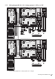
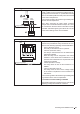
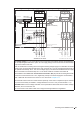
Legend
A1 Continuous humidity controller (active) or humidity sensor
A2 Ohmic humidity controller (passive), set jumper JP1 and remove jumper JP2
A3 On/Off humidity controller, set jumper JP2 and remove jumper JP1
A4 Limiter signal
A2 Ohmic limiter controller, set jumper JP1 and remove jumper JP2
B1 Ventilation interlock
B2 Airow monitor
B3 Safety humidistat
B4 External enable contact
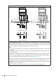
F1 Internal fuse 24V supply (1 A, slow acting)
F2 Internal fuse 230V supply (6.3 A, slow acting)
F3 External fuse heating voltage supply (see table in chapter 5.7.7)
F4 External fuse control voltage (max. 10 A, slow acting)
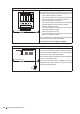
J1 Jumper wire, if blower pack safety loop is not connected
J3 Jumper wire, if no monitoring devices are connected to SC1 and SC2
J4 Jumper for activating the terminating resistor for Modbus network (Jumper must be connected, if Condair RS is the last
unit in the Modbus network)
J7 Jumper for activating Modbus or BACnet MSTP communication via RS485 interface (J6). If jumper is not in place no
communication will take place through the RS485 interface.
J8 Termination Linkup system (Jumper must be connected, if the Condair RS is the rst or the last unit in the Linkup system).
H1 Remote operating and fault indication (option)
H2 Accessory board (option) for the control of an external fan of the AHU as well as the optional external valve for the
water supply line ushing
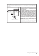
K1 Mains contactor (heating voltage) Main A / Main B and Extension A / Extension B
K2 External safety circuit (safety humidistat, airow monitor, etc.)
Q3 External main switch heating voltage supply
Q4 External main switch control voltage supply
SW1 Rotary switch Module identication (Module A: 0, Module B: 1)
THV Terminal Heating voltage supply (option)
Y1 Total drain valve (option)
1 Supply cable Module A to Module B - 1,65 m (supplied)
2 Data cable Module A to Module B - 1,65 m (supplied)
3 Linkup cable - 2,5 m (supplied)