
Installation Instructions


64 Mounting and installation work
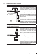
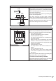
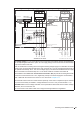
Connecting an ohmic humidity controller (passive)
140Ω...10kΩ
A2
CONTROL
V+ IN GND
JP2 (24V)
JP1 (10V)
Control compartment
The signal cable of an ohmic humidity controller
(140Ω...10kΩ) is to be connected according to the wir-
ing diagram to the terminals "V+", "IN" and GND" on
the driver board in the control compartment.
The connecting cable must be led through a cable gland
into the control compartment.
Note: when connecting an ohmic humidity controller
Jumper "JP2" must be removed and Jumper "JP1" must
be connected on the driver board and the control signal
type must be set to 0-10V in the control settings of the
control software.
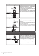
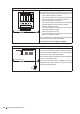
Connecting a 24V On/Off humidistat
On/Off
A3
CONTROL
V+ IN GND
JP2 (24V)
JP1 (10V)
Control compartment
The signal cable of 24V On/Off humidistat is to be
connected according to the wiring diagram to the ter-
minals "V+" and "IN" on the driver board in the control
compartment.
The connecting cable must be led through a cable gland
into the control compartment.
Note: when connecting a 24V On/Off humidistat Jumper
"JP1" must be removed and Jumper "JP2" connected.
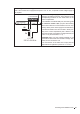
Limiter wiring
Connecting an external limiter controller or a humidity sensor
A4
LIMIT
IN GND
+ –
Z
Control compartment
The signal cable of an external limiter (P/PI continuous
controller) or of a humidity sensor (if the internal P/PI
limiter controller is used) is to be connected according to
the wiring diagram to the terminals "IN" (+) and "GND"
(–) on the driver board in the control compartment.
The connecting cable must be led through a cable gland
into the control compartment.
Note: the limiter must be activated and congured via
the control software accordingly. The admissible limiter
signal values can be found in the technical data table
in the operation manual.