
Installation Instructions


69Mounting and installation work
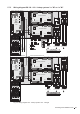
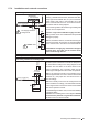
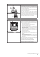
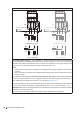
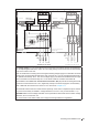
Connecting the heating voltage supply via option TR (for 3 phase single voltage system)
MAINS SUPPLY
L N SC1SC2PEPE
MODULE B
X7
X1
MAINS S
L N SC1
MODULE B
X7
X1
L1 L2 L3
K1
L2
L3
L1
PE
L1 N PE
F3
Q3
L2 L3
PE
L1
L1 L2 L3
F3
Q3
L2 L3L1
K1
L1
THV
L2 L3
400-500 V/3~/50..60 Hz 400-500 V/3~/50..60 Hz
6.3 A, slow acting
Option TR
Control compartment
(Module B)
Control compartment
(Module A)
Supply cable
(Module A / Module B)
The voltage supply (L1, L2, L3 and PE) is to be connected in accordance with the wiring diagram to
the corresponding terminals of the option TR. The supply wiring is to be fed into the unit via the clamp
strap on the bottom of the unit.
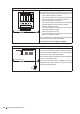
Note: On double units consisting of two housings the heating voltage supply for module B is connected
directly to the corresponding terminals of the main contactor "K1" or to the corresponding terminals of
the optional terminal strip "THV". The control voltage supply to module B is established via the supply
cable connected to the terminal strips "X7" on the driver boards of module A and module B.
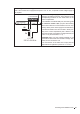
The installation of the fuses "F3" and the electrical isolator "Q3" (all pole disconnecting device with
a minimum contact clearance of 3 mm, supplied by others) in the mains supply line are mandatory.
Note: a table with the values for the fuses "F3" is to be found in chapter 5.7.7.
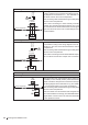
The electrical isolator must be mounted in direct proximity of the control compartment (max. distance
1 m) and must be easily accessible in a height between 0.6 m and 1.9 m (recommended: 1.7 m).
CAUTION! Make sure the voltage indicated on the specication label meets the local mains voltage.
Otherwise, do not connect the unit.
The cross-section of the mains cable must comply with the applicable local regulations.