
Owner manual


Maintenance and Service 19
3. Install new O-rings (28, 27) inside and outside of the valve stem seat. Coat all O-rings and back-up rings
(30, 31) with fluorinated Krytox grease before installation. Make sure that the rings are installed in the
proper order.
4. Install the valve stem seat (8) by grasping the small diameter end with the needle-nose pliers and
positioning in the valve cavity, then gently pushing with the blunt end of a drill bit.
5. For
COARSE (pressure) and VENT valves (two outer valves), disassemble the valve needle (11) from its
housing (10) and check for any burrs or dirt on the threads which might interfere with smooth operation.
6. Clean both the needle (11) and housing (10) in solvent, dry the parts and apply a small amount of
fluorinated Krytox grease to the needle threads before reassembly.
7. Assemble the valve needle (11) into the valve needle housing (10) and turn it until it stops.
8. Reinstall the needle/housing assembly into the valve cavity until finger tight.
9. Mount the manifold body (16) in a vise. For the
COARSE (pressure) and VENT valves only, torque the
needle/housing assembly to 325 in-lb. using the needle housing socket (PN 65580).
10. Install the housing lock nuts (1) onto the housing (10) and tighten until snug with the 3/4" socket.
11. Using the .050" hex wrench, install and tighten the lock nut (2) and set screw (34).
12. Install the knob insert (4) over the valve needle (11) shaft, align the set screws (23) with the indents and
tighten with the .061" hex wrench.
13. For the
ISOLATION valves (two inner valves), install the needle housing (19) and tighten until snug using
the isolation valve housing installation socket (PN 68509) and torque wrench.
NOTE: There is no specified torque, so use care when tightening so as not to break the socket nibs.
14. Install the gear (6) over the isolation valve needle (18) shaft, align the set screws (26) with the indents
and tighten with the .061" hex wrench.
15. Apply a small amount of fluorinated Krytox grease to the threads of the
ISOLATION valve needles (18)
and install into the valve by turning counter-clockwise. Rotate the gear until the needle just stops at the
seat.
4.2.9 ORION-2C Manifold, Panel Installation
Tools required: 7/16" open end wrench
Phillips screwdriver
hex wrench (.061")
snoop, liquid leak gas detector (PN 64781)
11/32" open end wrench (thin)
1. If not already done, remove the panel knobs from the COARSE (pressure), VERNIER, and VENT valves
using the .061" hex wrench.
2. With the panel facing down against the bench, lifting up the chassis enough so that the ORION-2C
manifold is able to clear.
3. Install the manifold with the transducer port side facing the panel bottom. Install the two mounting
screws (PN 60837) from the panel front and tighten until snug.
4. Secure the chassis to the panel with the four nuts and tighten until snug.
5. Install the
VERNIER knob (17) onto the VERNIER valve shaft (14). Align the set screws (25) with the
indentations on the vernier valve shaft and tighten until snug using the .061" hex wrench.
NOTE: To install the COARSE (pressure) and VENT valve knobs,and do valve adjustment, follow the procedure in
Section 4.2.10 after completing the following steps.
6. Install the transducer into the manifold port, tighten with the 11/32" thin wrench and reconnect its wire
connector.
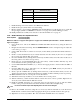
NOTE: If transducer is hard-wired, connect the four wires to the terminal block, TB1, on the CPU board (see Table 4-2
on page 20):