UPC5200 & UPC5210 Portable & Rack-mountable Pneumatic High Pressure Calibration Console Operation and Maintenance Manual CONDEC Sales Phone No. (888) 295-8475 CONDEC Web Site: www.4condec.
Contents About This Manual ................................................................................................................................... 1 1.0 Introduction.................................................................................................................................. 1 2.0 Operation...................................................................................................................................... 4 2.1 2.2 2.3 2.4 3.0 4 4 5 6 Calibration..........
5.0 Model Number System .............................................................................................................. 44 6.0 Ranges and Resolutions ............................................................................................................ 45 7.0 Options, Replacement Kits ........................................................................................................ 46 8.0 Specifications ..............................................................................
About This Manual This manual is intended for use by service technicians responsible for installing and servicing UPC5200/UPC5210 pressure calibrators. The UPC5200 portable pneumatic pressure calibrator and the rack-mounted UPC5210 are rugged, compact instruments manufactured by Condec. They are designed to provide superior accuracy, range of calibration and ease of operation when used for the calibration of a wide variety of pressure sensing and measuring devices.
• Calibration Integrity: Tamper-proof design. Once calibrated, numerous safeguards guarantee the integrity of pressure readings obtained. Display prompting provides the operator with functional status information during both operation and calibration. • Pressure Source (UPC5200 only): An external supply cylinder with a volume of 83.3 std. cu. ft. of N2 provides up to 2,216 psig of pressure for calibration and test.
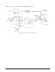
Figure 1-1 provides an overview of the UPC5200/UPC5210’s function. Figure 1-1.
2.0 2.1 Operation Pressure Cylinder (PN 59533) Filling Procedure NOTE: Condec strongly recommends that the external nitrogen supply cylinder be pressure-tested and re-certified every five years from date cylinder was manufactured per U.S. DOT. 3AL Regulation, Title 49 CFR, parts 173 and 178. To initially fill or refill the external pressure cylinder (2,216 PSI max.), proceed as described below. 1. Close the CYLINDER valve by rotating clockwise until it stops. 2.
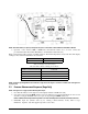
Figure 2-1. Initial Setup Procedure NOTE: UPC5200 shown, AC Input (7) and Input Port (4) are on back side of UPC5210 Rack Mountable Calibrator. 9. Optional - if the current (4.000 to 20.000 mA) measurement features are to be used, connect the provided Transducer Test Cable (PN 55092) to the Transducer Test Jacks (14). When connected, this cable provides +28 VDC excitation. The internal impedance (load) is 10 ohms.
4. Using the REGULATOR (1), adjust the maximum intensifier pump input pressure, as read by the REGULATED PRESSURE gauge (6), to 1/10 of the full-scale range of the device-under-test. The unit utilizes an internal intensifier with a 10:1 ratio. As an example, setting regulated pressure to 300 PSI would generate an output pressure of 3,000 PSI. Using this technique, the device under test is fully protected from being accidentally over-pressurized. 5.
2.2. Using the REGULATOR (1), adjust the maximum intensifier pump input pressure, as read by the REGULATED PRESSURE gauge (6), to 1/10 of the full-scale range of the device-under-test. The unit utilizes an internal intensifier with a 10:1 ratio. As an example, setting regulated pressure to 300 PSI would generate an output pressure of 3,000 PSI. Using this technique, the device under test is fully protected from being accidentally over-pressurized. 2.3.
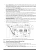
Figure 2-3. Pressure Measurement Sequence (Absolute Only) NOTE: UPC5200 shown, AC Input (7) and Input Port (4) are on back side of UPC5210 Rack Mountable Calibrator.
3.0 Calibration Follow the procedure on the following pages for calibrating the UPC5200/UPC5210. NOTES: • When calibrating, the computer within the UPC5000/UPC5010 is actually being re-programmed, therefore it is important that the pressure standard being used is in satisfactory operating condition and that the technician fully understands its operating characteristics and methods of usage.
3.3 Zero/Span Calibration Selecting the ZERO/SPAN position on the Condec Calibration Module (PN 60109) places the instrument into its ZERO/SPAN calibration mode. The display is shown in Figure 3-2. NOTE: Absolute only unit requires vacuum pump with PSIA test standard to obtain readings below local barometric pressure. Figure 3-2. Zero/Span Calibration for Gage Only Units Starting with the instrument's lowest pressure range, perform steps 1 and 2 shown in Table 3-1 for each pressure range.
Figure 3-3. Linearity and Hysteresis Calibration Starting with the instrument's lowest pressure range, sequentially perform the thirteen steps described in Table 3-2, for each pressure range being calibrated. Perform the following for each step: 1. Adjust input pressure to the appropriate value without overshooting the setting. If value is overshot by more than 1%, vent unit and repeat steps. 2. Perform the action as indicated when the readings are stable. Should not take longer than 15 minutes.
3.5 Shunt Resistor Calibration Install the Condec Calibration Module (PN 60109) and select the SHUNT position of the rotary switch on the module. This places the UPC5200/UPC5210 into its SHUNT RESISTOR calibration mode. The display is shown in Figure 3-4. Figure 3-4. Shunt Resistor Calibration With the UPC5200/UPC5210's highest pressure range selected, perform the four step sequence described below: 1. Gage Only Units: Be sure the input pressure to the UPC5200/UPC5210 is at 0 PSIG.
3.8 Normal Mode Test After completing the above calibration procedures, you must perform a normal mode test. A current generator capable of generating 20 mA must be connected to the COMMON and CURRENT INPUT jacks, see Figure 2.2 on page 4 (14). The DISPLAY SELECT switch (16) should be on the CURRENT position. 1. Set the Condec Calibration Module to the NORMAL MODE position. 2. DISPLAY SELECT switch should be in the CURRENT position. The display reads 20.000. 3.9 Self-Check Test 1.
4.0 Maintenance & Service This section outlines the mechanical and basic electrical repair procedures for the UPC5200/UPC5210. 4.1 Troubleshooting Use Table 4-1 below for information on troubleshooting the UPC5200/UPC5210. Symptom Problem Remedy Display does not light up. Unit will not energize. Check fuse, check power source, check power switch. Display slowly decreases over time. Leak in system.
Figure 4-1.
4.2.1 Panel/Chassis Removal and Installation UPC5200 Removal Tools required: Phillips screwdriver 1. Loosen and remove the 10 screws (PN 14862) that secure the panel assembly to the enclosure. 2. Lift the panel and chassis by first grasping the regulator knob and test port and second, grasping under the panel edges. Tilt the panel at an angle by lifting the right side before the left side as you face the panel. Ensure that the wire harnesses do not catch and snag. 3.
4. Loosen and remove the six screws that secure the two clamps that hold the intensifier and accumulator. 5. Remove the accumulator by sliding out. 6. Loosen the fitting nut at the intensifier end of the long 1/4" diameter tubing section that connects the solenoid valve to the intensifier. There is no need to remove the tubing. 7. Remove the two clamps and the intensifier. 8. Using a 7/16" wrench, remove the following tubing sections: • Vent port to ORION-3A manifold vent outlet (1/8" dia.) 9.
11. Blow out any chips from the seat area using compressed air. 12. While holding the 4-40 tap steady and perpendicular to the seat, slowly turn until the tap starts to engage the seat. 13. When the tap has engaged into the seat, use a small hammer and gently knock upward against the tap handle to extract the seat. 14. After the seat has been removed, blow any remaining chips from the seat area. 4.2.
7. Install the end bushing (12) and tighten until snug using the isolation valve needle housing socket (PN 68508) and socket wrench. 8. Tighten so that shaft rotates, but should be firm. Feel vertical motion of shaft (14). If motion exists, retighten end bushing. 9. Install the locknut (20) into end cap (13) and using the isolation valve needle housing socket (PN 68509) and torque wrench. Torque to approximately 325 in/lbs. (may not get to torque on all sub-assemblies). 10.
4.2.7 Accumulator, Intensifier and ORION-3A Manifold, Panel Installation NOTE: See Figure 2-1 on page 5, for the items listed in parenthesis. Tools required: 7/16" open end wrench Phillips screwdriver hex wrench (.061") Snoop®, liquid leak gas detector (PN 64781) 11/32" open end wrench (thin) 1. If not already done, remove the panel knobs from the COARSE (pressure), VERNIER and VENT valves using the .061" hex wrench. 2.
2. Energize the unit and let warm up. Turn RANGE SELECT switch to highest range. To adjust the COARSE valve, go to step 3. 3. Using a .050" hex wrench, loosen the set screw (34) on the locknut (2) and turn the locknut clockwise to its stop. 4. Check to see that the knob insert (4) is securely fastened to the valve shaft (11). If it is loose, re-tighten the set screws (23) with the .061" hex wrench. 5.
4. Remove O-ring (PN 58051) and back-up ring (PN 59735). 5. Remove accumulator body from vise and place adapter fitting in vise, using flats, threads facing upwards. 6. Remove filter retainer fitting (PN 57811) using wrench. 7. Remove plug adapter fitting from vise, turn up side down, and remove filter. 8. Clean the filter (PN 56993) in solvent (de-natured alcohol) and blow-dry with compressed air. Assembly: 1. 2. 3. 4. 5. Place filter (PN 56993) into filter retainer fitting (PN 57811).
Reassembly of Check Valves: NOTES: • Clean all parts with solvent and use shop air hose to remove any dust particles from all mechanical parts, except screws and washers. Wipe the bores of the intensifier housing with a clean cloth before installing the piston. Replace all damaged parts with new ones.
Reassembly of Rings and Seals: NOTE: Clean all parts with solvent and use shop air hose to remove any dust particles from all mechanical parts, except screws and washers. Wipe the bores of the intensifier housing with a clean cloth before installing the piston. Replace all damaged parts with new ones. 1. Smear a medium amount of grease in O-ring cavity on piston (18). Grease both sides of the two backup rings (20) and O-ring (21). Install into groove on piston (18).
4.2.11 Regulator (Standard Pneumatic) and Solenoid Removal Solenoid 120 VAC input - PN 56851, Solenoid 220 VAC input - PN 54366 Tools required: Phillips screwdriver 7/16" open end wrench 9/16" open end wrench A/R 1/4" wide teflon tape, (PN's 60575) A/R 1/2" wide teflon tape, (PN's 60911) 1/2" socket socket wrench 1/4" hex wrench NOTE: See Figure 4-4 on page 37. 1. Vent any remaining gas from the system to atmosphere. Disconnect the power cord from the power source. 2.
4.2.13 Regulator (Tescom) and Solenoid Removal Solenoid 120 VAC input - PN 56851, Solenoid 220 VAC input - PN 54366 Tools required: Phillips screwdriver 7/16" open end wrench 9/16" open end wrench A/R 1/4" wide teflon tape, (PN's 60575) A/R 1/2" wide teflon tape, (PN's 60911) 1/2" socket socket wrench 1/4" hex wrench flat blade screwdriver (small) channel locks NOTE: See Figure 4-4 on page 37. 1. Vent any remaining gas from the system to atmosphere. Disconnect the power cord from the power source. . 2.
7. 8. 9. 10. Turn the PUMP CONTROL switch (20) off when 1,000 PSI has been achieved. Check all fittings for leaks. If there are no leaks vent system and remove pressure source. Install panel/chassis assembly in its enclosure as described in Section 4.2.1 on page 16. Energize the unit and let warm up. Turn range select switch to highest range. Close the COARSE valve by turning the COARSE knob clockwise.
4.2.16 Test Port Quick-Connect Fitting (PN 59004) and Filter (PN 54188), Removal and Installation Every two months, a coating of flourinated Krytox grease should be applied to the inner seal of the test port fitting. The pressure cap (PN 58216) should be plugged in whenever the unit is not in use. NOTE: For simplest method, apply fluorinated krytox grease to the outside surface between sealing lip and end of mating pressure cap.
Installation: 1. Grease inside cavity on bottom flat (none allowed in hole) of quick-connect fitting (PN 59034). 2. Grease O-ring seat groove area in filter fitting (PN 59588). 3. Grease both sides of O-ring (PN 55608). While holding filter fitting (PN 59588) vertically, place O-ring (PN 55608) and then filter (PN 56991) into filter fitting (PN 59588). 4. Thread quick-connect fitting (PN 59034) onto filter fitting (PN 59588). 5.
6. Inspect and clean parts in solvent (de-natured alcohol) and blow-dry with compressed air. Replace worn or damaged parts with new ones. Installation: 1. 2. 3. 4. Wrap two turns of 1/2" Teflon Tape around threads of CGA-580 Nipple (PN 57150) pressure fitting. Hold CGA-580 nipple (PN 57150) pressure fitting in vise by flats located on nipple. Slide CGA-580 nut (PN 57154) over threads of CGA-580 nipple (PN 57150) pressure fitting.
Connect wires to the three wire side of new line filter as follows: Green/Yellow wire to AC INPUT Green wire from terminal (E) Ground Blue wire to AC INPUT White wire from terminal (N) Neutral Brown wire to pump control board, black wire from TB3 terminal HI NOTE: Some units may have POWER marking in place of AC INPUT on panel. 4.2.
Terminal Normally open (C) common Color Black Black 2. Pull shrink sleeving over switch and connections. Apply heat. Install the new switch, lock washer and nut through the panel rear as one item. Hand tighten the trim ring from front of panel. 3. Tighten the switch mounting nut and lock washer from the rear of panel. CAUTION: If wrench is used, do not over tighten, damage may occur to switch. 4. Install panel/chassis assembly in its enclosure as described in Section 4.2.1 on page 16. 4.2.
Installation: 1. Connect and solder the wires onto their respective switch terminals: Zero: Terminal Color Normally open (C) common Yellow Green 2. Install the new switch, lock washer and nut through the panel rear. Hand tighten the trim ring from front of panel. 3. Tighten the switch mounting nut and lock washer from the rear of panel. Replace CPU if necessary. CAUTION: If wrench is used, do not over tighten, damage may occur to switch. 4.
4.3 ORION-3A Valve Assembly (55287) Parts List The following table lists the component parts of the ORION-3A.
Figure 4-2. ORION-3A Part No.
4.
Figure 4-3. Intensifier Exploded View Figure 4-4.
REVISIONS REV REFERENCE AF ECO10483: DELETED ITEMS 10 & 11; REDRAWN ON RLW FORMAT AG DELETED ITEM NUMBER 2 . ECO11898: ADDED NOTE 27, ADDED INFO TO ITEM NO. 101 ON AH LIST OF MAT'L, ADDED INFO TO ITEM 31, ADDED NOTE 28 AND 29, REMOVED SPEC. FROM ITEM 61, 62, 65 AND 1 THRU 54 28- KEU8924-1 (54254) & KEU8924-3 (54263) ONLY: ON CIRCUIT SIDE OF BOARD, CUT CLAD BETWEEN CR12 ANODE AND VIA UNDER U10. CUT CLAD BETWEEN CR10 ANODE AND U6-4. ADD 3 1/2" 30 AWG WIRE, ITEM 101, BETWEEN CR10 ANODE AND VIA UNDER U10.
Figure 4-6.
Figure 4-7.
Figure 4-8.
Figure 4-9.
Figure 4-10.
5.
6.0 Ranges and Resolutions NOTE: Display resolution, 0.02% of selected range, unless it is not devisable by 1, 2, or 5. RANGE (PSI) HI/MED/LO Calibrator Mode RESOLUTION HI/MED/LO 10000/5000.0/2000.0 Gage Only 2/1/0.5 5000.0/2500.0/1000.0 Gage Only or Absolute Only 1/0.5/0.2 Table 6-1.
7.0 Options, Replacement Kits There are numerous replacement part numbers mentioned throughout manual that can be ordered. ORION-3A O-Ring Replacement Kit (Data Sheet # 65370): • Fluorocarbon “Viton” (standard)...........................................................PN 55277 • Nitrile Buna-N.......................................................................................PN 58499 • Ethylene-Propylene ...............................................................................PN 58506 • Silicone.
8.0 Specifications Pressure Specifications: Pressure range: Three independent pressure ranges per instrument. See Section 5.0 on page 44 for available ranges. Available pressure calibrations: Gage only or absolute only, Overall accuracy: < ±0.05% Full Scale Max. Accuracy statement includes all effects of linearity, hysteresis, repeatability and ambient temperature Operating Temp: +40° to +122°F (+4.4° to +50.0° C) Storage Temperature: 0° to +185° F (–17.
Control Panel: Material: Thickness: UPC5200 Finish: UPC5210 Finish: 48 Aluminum (5052-H32) 0.125 in. Gray enamel paint with black silkscreen nomeclature Dark Tan enamel paint with black silkscreen nomenclature Physical Specifications: Weight: 52 lbs. including all hoses and cables. UPC5200 Case Dim’s: 11" wide x 18" long x 11.5" high UPC5210 Case Dim’s: 19" wide x 8.1" deep x 10.5" high (Case Dimensions excluding front handles).
UPC5200/UPC5210 Warranty and Return Policy If possible, please save original packing material which is specifically designed for the unit. Should it be necessary to ship the unit back to the factory, a suitable shipping container must be used along with sufficient packing material. Do not put a shipping label on the unit as a "suitable shipping container." Some units have been severely damaged this way. This is a delicate, precision instrument.
UPC5200/UPC5210 Return Material Authorization Form The repair lab is also equipped to do calibrations on our calibrators and pressure standards. Calibrations include a certification and are traceable to N.I.S.T.