UPS3000, UPS3110 & UPS3210 Portable & Rack-mountable Pneumatic Pressure Standards Operation & Maintenance Manual CONDEC Sales Phone No.: (888) 295-8475 CONDEC Web Site: WWW.4CONDEC.
UPS3000/UPS3110/UPS3210 Operation and Maintenance Manual
Contents 1.0 Introduction.................................................................................................................................. 2 2.0 Operation...................................................................................................................................... 4 2.1 2.2 2.3 2.4 Unpacking and Inspection . . . . . . . . . . . . . . . . . . . . . . . . . . . . . . . . . . . . . . . . . . . . . . . . . . . . . . . . .
.2.12 4.2.13 4.2.14 4.2.15 4.2.16 4.2.17 4.2.18 4.2.19 4.2.20 4.2.21 4.2.22 4.2.23 4.2.24 4.2.25 4.2.26 4.2.27 Pressure Limit Control (Tescom), Regulator Removal . . . . . . . . . . . . . . . . . . . . . . . . . . . . . . . . . . . . . 37 Pressure Limit Control (Tescom), Regulator Installation . . . . . . . . . . . . . . . . . . . . . . . . . . . . . . . . . . . . 37 Panel Gauge Removal . . . . . . . . . . . . . . . . . . . . . . . . . . . . . . . . . . . . . . . . . . . . . . . . . . . . . . . . . . . .
About This Manual The bench-top UPS3000 and the rack-mountable UPS3110 and UPS3210 pneumatic pressure standards are rugged, compact instruments manufactured by CONDEC. They are designed to provide superior accuracy, range of calibration and ease of operation when used to assist in the manufacture, test and/or calibration of a wide variety of pressure sensing and measuring devices.
1.0 Introduction Utilizing microprocessor technology, the UPS3000, rack-mountable UPS3110 and UPS3210 instruments offer a combination of features, performance, versatility and reliability not previously available in a single, self-contained pressure calibration instrument. The following list notes the features and benefits of each unit: • Three independent switch-selectable pressure ranges per instrument.
With all its sophistication however, a great deal of effort has been expended to make the instruments simple to operate and easy to calibrate. Two micro-metering valves and vernier are provided to control the UPS3110 pressure source while the digital display indicates precisely the magnitude of the applied test pressure. Also, a pair of simple push-button switches provide both “zeroing” of the pressure display and the selection of either the “Gage” or “Absolute” calibration mode.
2.0 2.1 Operation Unpacking and Inspection When received, carefully remove the instrument from its shipping container. A visual inspection of the instrument’s external surfaces should be performed immediately after unpacking. If obvious damage has been incurred during transit, the shipping agency and the distributor should be notified as soon as possible. Instructions as to how to proceed after assessment of the damage will then be determined.
Figure 2-1. UPS3000 Desktop/Panel-mountable Pressure Indicator Display/Keyboard Functions Figure 2-2.
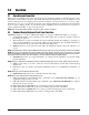
Figure 2-3. UPS3210 Rack-mountable Pressure Indicator Front Panel Functions 2.3 Rear Panel Configuration UPS3000 Series, See Figure 2-4 below, contains the following: 1. AC power cord, and input receptacle (17). 2. INPUT PRESSURE port J1 (16), 7/16-20, 37o-4 AN male fitting. #AUTION 3. 4. • • • Application of pressures greater than 1.5 times the highest pressure range of the indicator may cause calibration errors or even permanent damage to the pressure transducer.
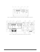
UPS3110 Rack-mountable Series, See Figure 2-5 below, contains the following: 1. AC power cord, fuse holder and input receptacle (17). 2. INPUT PRESSURE port (16), 7/16-20, 37o-4 AN male fitting. Location of port for AC only units. NOTE: The maximum input pressure, supplied by user, is noted below port. 3. The unit’s identification plate (15). 4. VENT/VACUUM PORT (19), 7/16-20, 37o-4 AN male fitting. 5.
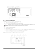
Figure 2-6. UPS3210 Rack-mountable Pressure Indicator Rear View 2.4 Configuration Switch Settings As normally supplied, the UPS3000, UPS3110 and UPS3210 will be fully calibrated and configured to the requirements specified by the customer purchase order. However, there are several functions or operational features that may be selected or altered by the operator during usage. These are controlled by the eight-position DIP switch, S1, located on the CPU board as shown in Figure 2-7.
2.4.1 APC4000/APC4001 Interface Option Enable Switch Settings S1 Position 1 Position 2 Position 3 Position 4 Position 5 Position 6 Position 7 Position 8 UPS 3000 UPS 3110 UPS 3210 0 0 1 0 0 0 1 1 With Controller 0 0 1 0 0 0 1 0 Without Controller Table 2-1. APC 4000/APC 4001 Interface Enable Switch Settings The APC4000 interface enable is activated only for models that are purchased and used with the PCM1000-1 controller or part of an APC4001 controller system.
2.4.3 Conversion Enable Switch Setting S1 Position 3 Front Panel Conv Key Mode 0 Disabled 1 Enabled Table 2-3. Conversion Enable Switch Setting As standard practice, the instruments are supplied with display indication in PSI (either Absolute, Gage or both) and capable of being converted to a range of nine units via the front panel CONV push-button switch.
2.5 Freeze Mode Option Wiring See Figure 2-7 on page 8 for TB location on CPU. Connections may be made using the Freeze Mode Kit, see “Freeze Mode Option - PN 57778” on page 54. The small five pin connector (pins A & B) which, in turn, are connected to the main CPU board via terminal block TB2-7 (+) (Pin A) and TB2-8 (Gnd Ret) (Pin B). The current through these wires is approximately 0.5 mA as a non-inductive load. The voltage between these two wires is 5 VDC.
2.6 Engineering Conversion with PEAK HOLD or MAX/MIN Option See Figure 2-7 on page 8 for location of “Data Enter” and rocker switches. NOTE: When the PEAK HOLD or MAX/MIN option is supplied with a model having the ABS/GAGE mode, switch selectable from front panel, the CONV button will be disabled and will not be present on the front panel. Figure 2-9. Peak Hold Option Front Panel Switches Figure 2-10.
2.7 UPS3000 or UPS3210 Initial Setup Sequence For UPS3000, refer to Figure 2-1 on page 5 and Figure 2-4 on page 6. For UPS3210, refer to Figure 2-3 on page 6 and Figure 2-6 on page 8. 1. Connect the pressure source to the instrument via the INPUT PRESSURE port (16), 7/16-20, 37o-4 AN male fitting provided on the rear panel. It is suggested that a Cheat Seal, PN 54854, be used between INPUT PRESSURE port and pressure source fitting.
2.8 UPS3110 Initial Setup Sequence Refer to Figure 2-2 on page 5 and Figure 2-5 on page 7. 1. Connect the pressure source to the instrument via the INPUT PRESSURE port (16), 7/16-20, 37o-4 AN male fitting provided on the rear panel. It is suggested that a Cheat Seal, PN 54854, be used between INPUT PRESSURE port and pressure source fitting. 2. Check that the INPUT valve (10) is closed (rotate clockwise until it stops) and that the VENT valve (12) is open (two turns counter-clockwise from its stop). 3.
2.8.2 UPS3110 Pressure Measurement Sequence Absolute (ABS) Mode NOTE: If local barometric pressure is not 14.7, ABS/GAGE switch selectable units only, may need barometric offset. See “Barometric Offset - Absolute/Gage Switch Selectable Units ONLY” on page 23. 1. If only pressure measurements greater than barometric are required, continue to step 1.1. If pressure measurements above and below atmospheric pressure are required go to step 2.
2.10 Battery Operation For replacement, see “Replacement Kits” on page 57. When supplied with the battery, the UPS3000/UPS3110/UPS3210 has an internal, rechargeable 12 volt, lead acid battery which provides a minimum of 6 hours of completely portable usage before having to be re-charged. The UPS3000/UPS3110/UPS3210 may be operated and/or recharged by simply connecting to a standard AC outlet via the line cord supplied.
5. At this time, record the settings of switch S1. These settings must be changed in order to program the serial output configuration. 6. After the data format and baud rate have been selected, refer to the “SERIAL OUTPUT CONFIGURATION TABLE” in this section for the appropriate values for the M.S.D. “M” and the L.S.D. “L.” 7. Set up switch S1 with the data derived from the “Serial Output Configuration Table”. 8. After switch S1 has been set, push the ENTER button on front panel to enter the data. 9.
2.11.4 SERIAL OUTPUT CONFIGURATION TABLE EEPROM LOCATION 64 64__ML S1 Settings LSD M 1 2 3 4 Serial Output Data Format 0 0 0 0 0 Format #1 Demand 1 1 0 0 0 Format #2 Demand 2 0 1 0 0 Format #1 Continuous 3 1 1 0 0 Format #2 Continuous Table 2-8. M Serial Output Configuration S1 Setting LSD L 5 6 7 8 Serial Output Baud Rate 0 0 0 0 0 300 1 1 0 0 0 600 2 0 1 0 0 1200 3 1 1 0 0 2400 4 0 0 1 0 4800 5 1 0 1 0 9600 Table 2-9.
3.0 Calibration and Adjustment Procedure The simple step-by-step calibration sequence provided on the following pages will permit a qualified technician to calibrate an entire UPS3000, UPS3110 or UPS3210 instrument in a matter of 45 minutes.
3.2 Instrument Calibration Set-Up NOTE: See“Case Removal and Installation” on page 28 and Figure 2-7 on page 8 to locate DIP switch S3 on CPU board. UPS3000 is placed into its calibrate mode by momentarily opening instrument drawer and setting the DIP switch, S3 in accordance with Table 3-1. Connect Test Standard to UPS3000 Input Port. UPS3110, disconnect the input pressure and power lines and remove the unit from its rack. Remove the top cover.
3.3 Zero/Span Calibration Pressing the STEPPER push-button switch once places the instrument into its ZERO/SPAN calibration mode. The display will be shown in Figure 3-3. Figure 3-3. Zero/Span Calibration for Gage Only Units (Each Range) Starting with the instrument’s lowest pressure range, sequentially perform steps 1 and 2 shown in Table 3-2 for each pressure range. Perform the following for each step. NOTE: Perform Step 1 in all ranges prior to doing Step 2. 1.
2. Perform the action as indicated when the readings are stable. INPUT PRESSURE, % OF RANGE OPERATOR ACTION REQUIRED STATUS SYMBOL IN LEFT MOST DIGIT REMARKS STEP NO.
3.5 Shunt Resistor Calibration Press the STEPPER push-button again to select the SHUNT RESISTOR CALIBRATION mode. The display will be as shown in Figure 3-5. Figure 3-5. Shunt Resistor Calibration With the UPS3000/UPS3110/UPS3210’s highest pressure range selected, perform the four step sequence described below: 1. Be sure the input pressure to the UPS3000/UPS3110/UPS3210 is at zero psig. NOTE: For Absolute Only Unit, vacuum pump with PSIA indicator must be used to obtain zero reading. 2.
3.7.1 For UPS3000/UPS3210 Absolute/Gage Switch Selectable Units ONLY If the current barometric pressure is below 14.7 PSIA, the offset is positive, see Example 1. If the current barometric pressure is above 14.7 PSIA, the offset is negative, see Example 2. If the current barometric pressure is 14.7 PSIA, then no offset is needed. Example 1: If the current barometric pressure is lower than 14.70 PSIA, subtract the current barometric pressure from 14.70. 14.70 PSI: UPS3110 reference point -14.
Example 2: If the current barometric pressure is above 14.70 PSIA, subtract the current barometric pressure from 14.70. 14.70 PSI: UPS3110 reference point -14.75 PSI: Current barometric pressure -.05 PSI: Negative Delta Offset Figure 3-6. Vacuum Pump Setup Complete the following steps: NOTE: UPS3000 refer to Figure 2-1 on page 5 and Figure 2-4 on page 6. UPS3210 refer to Figure 2-3 on page 6 and Figure 2-6 on page 8. 1. Connect Vacuum Test Standard to UPS3000/UPS3210 Input Port similar to Figure 3-6.
3.7.2 For UPS3110 Absolute/Gage Switch Selectable Units ONLY If the current barometric pressure is below 14.7 PSIA, the offset is positive, see Example 1. If the current barometric pressure is above 14.7 PSIA, the offset is negative, see Example 2. If the current barometric pressure is 14.7 PSIA, then no offset is needed. Example 1: If the current barometric pressure is lower than 14.70 PSIA, subtract the current barometric pressure from 14.70. 14.70 PSI: UPS3110 reference point -14.
value of the Negative Delta Pressure, -0.05 PSI as in this example. 6. Depress the ENTER push-button on the UPS3110. The display reads zero. Without touching the VERNIER (11) knob repeat this step for the middle and high ranges. 7. Using the STEPPER push-button, as shown in Figure 3-2 on page 20, place the unit into SHUNT RESISTOR CALIBRATION mode. The display will be as shown in Figure 3-5 on page 23. 8.
4.0 4.
UPS3110/UPS3210 Removal/Installation Removal Tools required: Phillips screwdriver 1. Vent system and remove input pressure source. Disconnect power cord, hoses, connectors, etc. from rear of UPS3110/UPS3210. Remove from rack, if applicable, by grasping the handles located on the front of the unit and gently set the rack-mount assembly on a bench top. It can be rested on the panel bottom and chassis edge. 2.
4.2.3 ORION Manifold - Valve Seat Removal ORION 2C: Refer to “ORION 2C Valve Assembly Parts List” on page 45 and Figure 4-1 on the following foldout 11 x 17 sheet. ORION 3A: Refer to “ORION 3A Valve Assembly Parts List” on page 47 and Figure 4-2 on the second foldout 11 x 17 sheet.
4.2.4 ORION Manifold - Vernier Control Disassembly ORION 2C: Refer to “ORION 2C Valve Assembly Parts List” on page 45 and Figure 4-1 on the following foldout 11 x 17 sheet. ORION 3A: Refer to “ORION 3A Valve Assembly Parts List” on page 47 and Figure 4-2 on the second foldout 11 x 17 sheet. Tools required: A/R solvent (de-natured alcohol) 1-1/4" open end wrench Screwdriver (flat-blade) Socket wrench Isolation valve needle housing socket (PN 68508) Isolation valve needle housing socket (PN 68509) 1.
4. 5. 6. 7. 8. 4.2.6 Install the end bushing (12) and tighten until snug using the isolation valve needle housing socket (PN 68509) and socket wrench. ORION 3A: Hold shaft (14) vertically with end that goes through end bushing (12) toward ceiling. Place light coating of grease on threads of shaft. Place thick coating of grease on top of shaft bearing surface. Place 16 ball bearings on shaft surface. Allowing grease to hold ball bearings in place.
11. Using the .050" hex wrench, install and tighten the lock nut (2) and set screw (34). 12. Install the Knob Insert (4) over the Valve Needle (11) shaft, align the Set Screws (23) with the indents and tighten with the .061" hex wrench. 13. For the Isolation Valves, (two inner valves), Install the Needle Housing (19) and tighten until snug using the Isolation Valve Housing Installation Socket (PN 68509) and Torque wrench.
4.2.8 ORION 2C Manifold - Valve Adjustment Procedure For UPS3110 Models with a Maximum Range 2000 PSI and below. ORION 2C: Refer to “ORION 2C Valve Assembly Parts List” on page 45 and Figure 4-1 on the following foldout 11 x 17 sheet. Tools required: Hex wrench (.050") Hex wrench (.061") Snoop, leak gas detector (PN 64781) NOTE: * denotes reference to Figure 2-2 on page 5. 1. If not already done, remove the ORION Input and Vent Valve Knobs (3) using the .061" hex wrench. 2.
4.2.9 ORION 3A Manifold - Valve Adjustment Procedure For UPS3110 5000 PSI and above Models. ORION 3A: Refer to “ORION 3A Valve Assembly Parts List” on page 47 and Figure 4-2 on the second foldout 11 x 17 sheet. Tools required: Hex wrench (.050") Hex wrench (.061") Snoop, leak gas detector (PN 64781) NOTES: 1. * denotes reference to Figure 2-2 on page 5. 2. Customer must supply, as a minimum, input supply pressure with a supply gauge and pressure regulator. 1.
4.2.10 Pressure Limit Control (Standard Pneumatic), Regulator Removal Tools required: Phillips screwdriver 7/16" Open end wrench 9/16" Open end wrench A/R 1/4" wide Teflon® tape, (PN’s 60575) A/R 1/2" wide Teflon tape, (PN's 60911) 1/2" Socket Socket wrench 1/4" Hex wrench NOTE: See Figure 4-1 on page 49. 1. Remove cover from its enclosure as described in Section 4.2.1 on page 28, and carefully place on a bench top. 2. Remove regulator knob cap. 3. Remove two screws that secure the round plate. 4.
4.2.12 Pressure Limit Control (Tescom), Regulator Removal Tools required: Phillips screwdriver 7/16" Open end wrench 9/16" Open end wrench A/R 1/4" wide Teflon tape, (PN's 60575) A/R 1/2" wide Teflon tape, (PN's 60911) 1/2" Socket Socket wrench 1/4" Hex wrench Flat blade screwdriver (small) Channel locks NOTE: See Figure 4-1 on page 49. 1. Remove cover from its enclosure as described in Section 4.2.1 on page 28, and carefully place on a bench top. 2.
NOTE: If pressure cannot be attained loosen locknut on shaft, rotate knob a few turns counter-clockwise, retighten locknut. If you hear the pressure relief valve then rotate regulator knob counter-clockwise until relief valve shuts off. 11. Remove locknut from threaded shaft, and rotate knob counter-clockwise until bottoming out on large locknut. After touching large locknut rotate knob clockwise 1/8 turn.
4.2.16 Test Port Quick-Connect Fitting (PN 59762) Removal and Installation - 15, 50 and 100 Full Scale PSI Models UPS3110[]DA, UPS3110[]DB, UPS3110[]EA, UPS3110[]EB and UPS3110[]JA only. If there is leakage out of the port, replace the test port fitting. Tools required: Phillips screwdriver 5/8" Two open end wrenches 9/16" Open end wrench Snoop, liquid leak gas detector (PN 64781) 1. Remove cover from its chassis as described in Section 4.2.1 on page 28, and carefully set on a bench top. 2.
4.2.18 Test Port Filter (PN 54188), Removal and Installation - 500, 1000 and 2000 Full Scale PSI Models UPS3110[]B[], UPS3110[]C[] and UPS3110[]F[] only. The port filter is a sintered element filter which is easily removed for inspection and cleaning. Tools required: Phillips screwdriver 7/16" Open end wrench 9/16" Open end wrench A/R Solvent (de-natured alcohol) Snoop, of liquid leak gas detector (PN 64781) Test Port Filter Removal 1. Remove cover from its enclosure as described in Section 4.2.
4.2.20 Test Port Quick-Connect Fitting (PN 59004) and Filter (PN 54188) Removal and Installation - 5000 and 10000 Full Scale PSI Models UPS3110[]A[], and UPS3110[]GA only. Every two months, a coating of fluorinated Krytox grease should be applied to the inner seal of the test port fitting. The pressure cap (PN 58216) should be plugged in whenever the unit is not in use. NOTE: For simplest method, apply fluorinated Krytox grease to the outside surface between sealing lip and end of mating pressure cap.
4.2.22 AC Power/EMI Line Filter (PN 58870), Removal and Installation Tools required: Phillips screwdriver 1/4" Open end wrench or nutdriver A/R soldering iron A/R shrink sleeving (PN 60735) A/R heat gun 1. Disconnect the power cord from the power source and line filter. Remove front panel from its enclosure as described in Section 4.2.1 on page 28, and carefully set on a bench top. 2. Remove the three cable connectors from the line filter terminals.
Installation: 1. Slide shrink sleeving over wires, connect and solder the wires onto their respective switch terminals: Terminal Color Normally open Black (C) common Black 2. Pull shrink sleeving over switch and connections. Apply heat. Install the new switch, lock washer and nut. 3. Tighten the switch mounting nut and lock washer from the rear of panel. #AUTION Do not over tighten if using wrench. Doing so could result in damage to the switch. 4.
4.2.27 BATTERY (55851), Removal, Installation and Adjustments Tools required: Phillips screwdriver Flat blade screwdriver (small) 11/32" Open end wrench or nutdriver 1. Disconnect the power cord from the power source and line filter. Remove cover from its enclosure as described in Section 4.2.1 on page 28, and carefully set on a bench top. 2. Disconnect the 2 battery cable wires from the battery terminals, Red wire from (+) and Black wire from (-). 3.
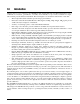
4.3 ORION 2C Valve Assembly Parts List The following table lists the component parts of the Orion 2C and the pullout 11x17 drawing on the next page illustrates the Orion 2C exploded view of those parts.
46 UPS3000/UPS3110/UPS3210 Operation and Maintenance Manual
THESE COMPONENTS TO BE INST ALLEDATAT LOCA TIONS A &DA & D INSTALLED LOCATIONS 38 16 10 1 2 33 25/2X 34 23/2X 4 D C 7 32 24/3X 9 3 28 31 15 27 35/2X 20 30 8 12 41 OR B 5 42 17 7 21/14 X 11 14 A 27 9 28 36 41 26/2X 31 OR 42 27 29 30 8 13 19 18 6 Orion 2C Exploded View Figure 4-1 THESE COMPONENTS TO BE THESE BE INSTALLEDATAT LOCA TIONS B A &C DB &C INSTALLED LOCATIONS 25/2X
4.4 ORION 3A Valve Assembly Parts List The following table lists the component parts of the Orion 3A and the pullout 11x17 drawing on the next page illustrates the Orion 3A exploded view of those parts.
48 UPS3000/UPS3110/UPS3210 Operation and Maintenance Manual
43 THESE COMPONENTS TO BE INSTALLED AT LOCATIONS A & D 16 10 C 1 2 33 D 25/2X 34 7 9 23/2X 28 1 4 2 32 24/3X 1 3 2 31 15 27 35/2X 1 20 30 2 8 12 B 5 41/16X 22/14X 7 A 21/14X 17 11 27 14 1 1 28 2 1 1 26/2X 31 2 36 2 38 30 2 8 NOTES: 1 41/16X 27 1 42/3X LIGHTLY COAT THE FOLLOWING WITH LUBRICANT, PN 55593 O-RINGS, ITEMS 27, 28, 29, 32 & 40. THREADS ON VALVE NEEDLES, ITEMS 11 & 18. FOR REFERENCE ONLY: O-RING, ITEM 27, .239 ID O-RING, ITEM 28, .
Figure 4-3. Tescom and Standard Pneumatic Regulator Mounting 4.5 UPS3000 Assembly Drawings The following table lists assembly drawings included with this manual.They’re included at the back of this manual.
5.0 Model Number System 5IF QBSU OVNCFSJOH TZTUFN JT EFmOFE BT GPMMPXT 614 @@@@@@@@@ @@@@@@@@@@ @@@@@@@@@ 614 @@@@@@@@@ @@@@@@@@@@ @@@@@@@@@ 614 @@@@@@@@@ @@@@@@@@@@ @@@@@@@@@ 108&3 3&26*3&.
6.0 Available Ranges, Multi-Conversions and Resolutions Approximately 1994 multi-conversion software was added to UPS3000 models, therefore UPS3000 and PCM1000 units made prior to this will not work with the ones manufactured after that date. Consult factory for information on upgrading units manufactured prior to 1994.
NOTE: Display resolution, 0.02% of selected range, unless it is not devisable by 1, 2, or 5. The following tables illustrate the various display resolutions associated with the various PSI conversion ranges. Conversion Ranges, HI/MED/LO PSI 20000.0/10000.0/4000 5/2/1 Bar 1379.0/689.5/275.80 0.2/0.1/0.05 40720/20360/8144 10/5/2 1406.2/703.1/281.25 0.2/0.1/0.05 in Hg 2 Kg/cm Conversion Resolution HI/MED/LO PSI 10000/5000/2000.0 2/1.0/.5 Kpa 68950/34475/13790 10/5/2 Bar 689.5.344.75/137.
Conversion Ranges, HI/MED/LO Resolution HI/MED/LO PSI 500.0/250.00/100.00 0.1/0.05/0.02 Kpa 3447.5/1723.6/689.5 0.5/0.2/0.1 25855/12928/5171 5/2/1 mm Hg Bar 34.475/17.236/6.895 0.005/0.002/0.001 in Hg 1018.0/509.0/203.6 0.2/0.1/0.05 mBar 34475/17236/6895 5/2/1 35155/17576/7031 5/2/1 Kg/cm 35.155/17.576/7.031 0.005/0.002/0.001 in H2O 13856/6928/2771.0 2/1/0.5 cm H2O 2 Conversion Ranges, HI/MED/LO Resolution HI/MED/LO PSI 100.00/50.00/20.000 0.02/0.01/0.005 Kpa 689.5/344.
7.0 Options, Replacement Kits There are numerous replacement part numbers mentioned throughout manual that can be ordered. 7.1 Freeze Mode Option - PN 57778 NOTE: This option may not be used with APC 4000 or APC4001 interface option. See “Freeze Mode Option Wiring” on page 11 for wiring information.
To use this option, select the appropriate pressure range using the Range Select switch. While the unit is at 0 psi, push the RESET button. Now run the pressure test. After the pressure test, push the RECALL button to display the “Peak” pressure during this particular test.The RECALL button may be pushed as many times as needed. Pushing the RESET button will clear the register and another pressure test may begin.
7.4 Analog Output Option (0 VDC to +10 VDC) NOTE: Recommended factory installed option. Also consult factory for battery models with this option.
7.6 RS232 Simplex Output Option Mode UPS3000A[][], UPS3000C[][], UPS3210A[][], UPS3110C[][], UPS3110A[][], UPS3210C[][] use PN 57788 NOTE: This may not be used with the following options in “DEMAND FORMAT”, APC 4000 or APC4001 interface, Peak hold, Min/Max or Battery. This may not be used with the following options in “CONTINUOUS FORMAT”, APC 4000 or APC4001 interface or Battery. Their are two modes of operation, Continuous or Demand. Continuous Mode: Model is continuously sending data.
• APC4001 Interface Cable Kit.............................................................................PN 55590 NOTE: Used with model’s APC4001 & UPS3110 only. The kit is a replacement cable available for UPS3110 units that were purchased in conjunction with CONDEC APC4001 pressure controllers. • Battery Replacement Kit.....................................................................................
8.0 Specifications Pressure Specifications: UPS3110 Internal Piping: Pressure range: Tubing: Three independent pressure ranges per instrument. See “Model Number System” on page 50 for available ranges. Available pressure calibrations: Gage only, absolute only, or gage and absolute Overall accuracy: < ±0.05% Full Scale Max. Accuracy statement includes all effects of linearity, hysteresis, repeatability and ambient temperature Operating Temperature: +40° to +122°F (+4.4° to +50.
Pressure to Digital Conversion: Conversion rate: Data updated at the rate of twelve (12) times per second, nominal. Display Resolution: Nominally 0.02% of F. S. for each pressure range displayed. Minimum Display Increments: To maintain virtually constant resolution, pressure increments of1,0.5, 0.2, 0.1, 0.05, 0.02, & 0.01 psi utilized as required. Accuracy/Resolution Ratio: A ratio of approx. 3:1 is maintained for all pressure ranges displayed.
UPS3000/UPS3110/UPS3210 Warranty and Return Policy If possible, please save original packing material which is specifically designed for the unit. Should it be necessary to ship the unit back to the factory, a suitable shipping container must be used along with sufficient packing material. If at any time, the instrument must be returned for repair, recalibration or modification, please be sure that a description of the work to be performed is included.
UPS3000/UPS3110/UPS3210 Return Material Authorization Form The repair lab is also equipped to do calibrations on our calibrators and pressure standards. Calibrations include a certification and are traceable to N.I.S.T.