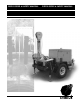
USER'S GUIDE & SAFETY MANUAL USER'S GUIDE & SAFETY MANUAL APS75 Underground Pulling Trailer
Important Safety Notice Read and understand all procedures and safety instructions before using a Condux Underground Pulling Trailers. Observe all safety information on this page and note specific safety requirements as explained by procedures in this manual. Failure to follow these instructions could result in serious personal injury or death. ADVERTENCIA: Favor de leer y comprender todas las instucciones de operación y seguridad antes de usar la máquina. Si Ud.
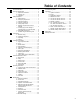
Table of Contents 1 2 3 4 5 6 7 8 General Information...................................................... 4 Technical Specifications............................................... 6 A. Operational Conditions............................... 6 B. Hydraulic Oil............................................... 6 C. Calibration.................................................. 6 Safety Information........................................................ 7 A. Safety Devices...................................
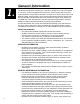
1. General Information PRODUCT DESCRIPTION The APS75 pulling trailer provides up to 7,500 lbs of pulling force, and a max speed of 170 ft/min. It comes equipped with an Electronic Control system which monitors system pressures, engine data, pull distance and pull force. Tension Limit control, Pull Data Recording, and HP limiting, which controls pull speed to eliminate engine stall, are also standard. The APS75 Pulling Trailer includes an engine noise reduction kit and 2600 feet of 3/8" anti twist rope.
• All maintenance operations, both scheduled and repair, must be carried out per the instructions included in this manual or following technical instructions provided by the manufacturer. Failure to follow these instructions relieves the manufacturer from any responsibility and voids their warranty.
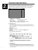
4. 2. Technical Specifications The Condux APS75 Hydraulic Underground Pulling Trailer provides up to 7500 lbs of continuous pulling force. Designed for installing underground cable, the APS75 is completely self-contained and transports easily from jobsite to jobsite. Industry leading features like a standard Electronic Control System, a mobile joystick, and antiwist rope make the APS75 the most advanced puller in the market today.
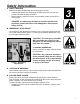
Safety Information A. SAFETY DEVICES Machine has been equipped with the following safety devices: • A load-limiting device that automatically disables the pump once the max. pre-set load value has been exceeded • Where possible, guards and covers are provided to protect personnel from moving parts 3. 3. !DANGER: it is absolutely forbidden to use this machine with protective guards removed or with damaged or disconnected safety devices. B.
• Assume only the recommended operation locations indicated in this manual (Figure 2) !WARNING: Rope failure can cause serious injury or death if safety precautions are not followed. Stay Clear Zones F. Rotating component pinch-point hazards Stay Clear Zones Due to the nature of the work being performed and important system functionality, it is not possible to fully guard all rotating components. Figure 2.
Transporting A. MACHINE LIFTING For machine lifting use only devices (overhead traveling cranes, lift trucks, ropes, cables, hooks, etc.) with a capacity equal to the weight to be lifted. Personel should not be on the machine when it is lifted. !DANGER: Failure to follow the recommendations in this section may create a dangerous situation and/or damage to the machine. The manufacturer’s warranty may also become void as a result. 3. 4. B.
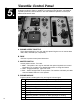
5. 5. Versatile Control Panel The Electronic Control and Monitoring system is an integral part of the APS75 Underground Pulling Trailer. In addition to monitoring pulling tensions, pull distance, hydraulic pressures, and fuel levels, it also also allows the operator to record pull data and set tension limits. F D I G B C G A H E J A. Engine Speed Throttle. Three detent settings for low, mid, and high speed. Engine runs no load at about 1000, 2200, and 3500 rpm, respectively B.
E. Electronic Controls and Display See Section 6 for detailed instructions and information F. filter lights Filter lights, F1 and F2 indicate that a hydraulic filter needs to be replaced. Replacement filters and maintenance instructions can be found in Section 12.A of this manual. G. Emergency Stop Buttons Emergency stop buttons are located on the main panel and on the mobile joystick. Pressing the E-Stop button will shut down the hydraulic circuit but will NOT shut off the engine.
5. 6. Advanced Electronic Control The Electronic Control and Monitoring system is an integral part of the APS75 Underground Pulling Trailer. In addition to monitoring pulling tensions, pull distance, hydraulic pressures, and fuel levels, it also also allows the operator to record pull data and set tension limits. A. Main Screen The Main Screen displays everything the operator needs to see during the course of a pull (Figure 2).
3. clock set - This screen displays Date and Time. Press and hold 56 together to enter EDIT mode. Use the 4 button to move between units. Use the 56 to change the value of each unit. NOTE: Recorded data is time stamped, so it is important to have the clock set in order to be able to match data to a specific pull (Figure 5). 4. raw data - Displays raw data for trouble shooting purposes. The data shown is Work Pressure, Charge Pressure, Reel Pressure, Engine RPM, and Joystick Actuation. Figure 5.
• • Tension Limiting status is displayed in the upper right hand corner of the Main Screen (Figure 2) If Tension Limiting is turned ON, and the set tension limit is exceeded during a pull, the controller will disable the pump by forcing it to neutral. The Screen will display a red message instructing the user to return the joystick to Neutral. Press the button labeled RESET to return to the main screen. (Figure 8) NOTE: The system will not reset unless the joystick is in the Neutral position. E.
Operating Procedures It is essential that the APS75 Underground Pulling Trailer be properly set up before operation. Using the following procedure will allow the unit to be set up in a short period of time and yield optimum performance. A. POSITIONING THE TRAILER & LOWER BOOM Position the APS75 Puller within an approximate boom arm reach of the manhole or duct bank. After trailer is positioned, lower boom arm. 3. 7.
NOTE: The trailer may be disconnected from the tow vehicle or left connected depending on specific site conditions. After placing wheel chocks, stabilize the trailer using the five supplied adjustable leveling jacks - two on boom arm, two at rear of trailer, and one on trailer tongue. Raise and lower jacks by rotating crank handle (Figure 3). Adjust the two jacks on the boom arm until the arm is level to the ground. C. START PULLER Open the Control Panel lid on the side of the APS-75.
IMPORTANT: Always keep tension on the winch line when paying it out to prevent slack from developing in bull wheel. In typical applications, the winch line will need to be paid out to reach the work area first, i.e. manhole, duct bank, etc. The winch line can then either be pulled through duct bank with a pulling rope or tape, or installed with a Condux Winch Line Blower. E. PREPARE FOR PULLBACK Adjust the Maximum Tension Limit (if desired) to the desired maximum pulling tension value (measure in lbs).
5. 8. Maintenance A. GENERAL PRocedures !CAUTION: Any customer repairs not authorized by the manufacturer relieves the manufacturer of any responsibility for any resulting damage of property or injury to personnel. B. FLUID LEVELS Due to safety and/or regulatory reasons, this machine may arrive without hydraulic oil and fuel. Fill the levels as per the following table: Fluids Hydraulic oil level (Maintenance drawing, item 3) Quantity 79.5 l – 21.0 gal Engine oil level (see enclosed engine booklet) 3.
!CAUTION: Disposal of all drained system oils and fluids must be in accordance with local regulations. Fill the hydraulic oil using the filler spout designated on (Maintenance drawing, item 1). !CAUTION: Ensure that no foreign matter enters the system along with the oil; if possible filter the oil with a 10 µm filter. Replace the filter cartridge after 500 working hours and then, every 1500 hours (or at least annually). Check that the hydraulic oil filter lamp lights only during start-up.
H. ELECTRONICS NOTE When cleaning the machine, avoid direct spraying of water or steam on electronic components or the control panel. For the other periodic operations refer to the summary table for the ordinary maintenance. I. SUMMARY TABLE FOR ORDINARY MAINTENANCE This table lists the recommended service intervals for the systems noted.
Troubleshooting Guide PROBLEM: CAUSE: SOLUTION: Burned fuse Replace Run down battery (Light on Kohler Controller) Recharge or replace Disconnected contacts of the The diesel engine starter ignition system / starter doesn’t work. Oxidised contacts of the ignition system / starter Diesel engine doesn’t work. 3. 9.
PROBLEM: CAUSE: SOLUTION: Hydraulic oil temperature too low Allow oil to warm up by running the engine at idle for several minutes. The clogged filter The oil is too thick warning light turns on. with respect to the environmental conditions Clogged hydraulic oil filter Replace E-Stop has been pressed. Pull up depressed E-Stop Button. Follow instructions on Control Screen to reset the machine Tension Limit has been exceeded. Follow instructions on Control Screen to reset the machine.
PROBLEM: CAUSE: SOLUTION: Add engine oil Defective sensor Engine oil pressure too low – check contacts / (Light on Kohler Controller) replace Engine anomaly – technical assistance Add cooling liquid Diesel engine turns off Defective sensor during operations.
PROBLEM: The machine doesn’t reach the max. pull performances. CAUSE: SOLUTION: Diesel engine rpm not sufficient Speed up the engine Diesel engine decreases rpm and turns off Decrease pull on the joystick Excessive hydraulic oil temperature Wait for oil to cool. Hydraulic oil cooler should run automatically when oil temperature exceeds temp limit. Check the fuel filter Insufficient fuel feeding at diesel engine The machine doesn’t increase speed.
11. 10. Appendices QUICK REF. SERVICE & PARTS LIST A. Hydraulic Oil Filters Filter Code Manufacturer Part Number QTY Vendor Alternative Vendors F1 MP Filtri CSG 150 P10A 1 OilAir Products Donaldson P550251 NAPA 1860 F2 MP Filtri CSG 100 A06 A 1 OilAir Products Behringer BSO12806A38 b.
DEXRON II ATF 200 DONAX TM CASTROL MOBIL SHELL (ISO 3448) VG 33-VG 39 UNIVERSAL OIL ATF VISCOSITY TYPE TELLUS 22 TELLUS 32 DTE 24 HYSPIN AWS 32 HYSPIN AWS22 DTE 22 VG32 -10°C -30°C VG22 COLD ARCTIC VG68 TROPICAL 40°C+ VG100 -30°C VG150 -10âC COLD DTE 26 TELLUS 68 TELLUS 46 HYSPIN AWS 68 DTE 25 HYSPIN AWS 46 OMALA 150 MOBILGEAR 629 MOBILGEAR 627 OMALA 100 ALPHA SP 150 ALPHA SP 100 OMALA 220 MOBILGEAR 630 ALPHA SP 220 VG220 30°C TEMPERATE GEAR BOX SUGGESTED GENERA
d.
E. TRLR, APS-75 7500LB CABLE TRLR 10 11 16 12 15 14 3 13 5 6 1 4 8 7 2 9 TRLR,APS-75 7500LB CABLE TRLR 08771000-1 ITEM 1 2 3 4 5 6 7 8 9 10 11 12 13 14 15 16 PART NO 02289180 02290321 02290322 02290459 08771178 08771179 08771191 08771194 08771205 08771241 08771244 08771283 08771284 08771285 08771286 21033937 DESCRIPTION LIGHT,LICENSE PLATE W/BRKT REFLECTOR,SD MRKR RD(RED) 2.38 REFLECTOR,SD MRKR RD(AMB) 2.38 LIGHT,OVAL TAIL LED - KIT ROLLER,LEAD IN 8.5-NYL APS-75 ROLLER,LEAD IN 6.
F.
G. FAIRLEAD, LEVELWIND 3 4 1 2 FAIRLEAD,LEVELWIND 08771122 ITEM 1 2 3 4 PART NO 02021501 02288426 21011189 21032472 APS-75 DESCRIPTION LOCKWSHR 0.25 REGULAR ST CZ CAPSRW 0.25-20X1.
H. ARM, COMPLETE-ASSY APS-75 10 9 5 6 4 2 1 7 8 3 ARM,COMPLETE-ASSY APS-75 08771150 ITEM 1 2 3 4 5 6 7 8 9 10 32 PART NO 02010100 02021301 02288243 02288311 02288443 08771149 08771155 08771176 08771177 08771262 DESCRIPTION NUT 0.50-13 NYLOC ST GR5 CZ FLATWSHR 0.50 TYPEA-WIDE ST CZ RING,RETAINING 1.000 EXT(4100) CAPSRW 0.50-13X6.50 HHSTGR5 CZ SCREW,TAP .190-16X1.
I. ARM, BOOM PIVOT EXTENSN APS-75 6 1 7 4 2 5 3 ARM,BOOM PIVOT EXTENSN APS-‐75 08771155 ITEM 1 2 3 4 5 6 7 PART NO 02289141 02290577 08763155 08771158 08771170 08771224 08771258 DESCRIPTION PIN,HITCH .50" DIAM 4.0" GRIP RING,RETAINING 1.
J.
K. PANEL, CONTROL-ASSEM-APS75 PANEL,CONTROL-ASSEM-APS75 08771040 ITEM 1 2 3 4 5 6 7 PART NO 02290370 02290375 02290378 08771053 08771054 08771257 12002300 DESCRIPTION NUT #04-40 NYLOC ST GR2 CZ CAPSRW #04-40X.31 BHSS 18-8 SPRING,GAS-15LBS 3.54" STROKE CONTROL,REMOTE-ASSEY APS75 ENCLOSURE,CONTROL-TOP-ASSEM LABEL,INST-OPER APS75 NUT 0.
L. FAIRLEAD,CAPSTAN MOUNT APS-75 4 3 1 5 2 FAIRLEAD,CAPSTAN MOUNT APS-75 08771139 ITEM 1 2 3 4 5 36 PART NO 02290380 02290381 08771125 08771138 08771219 DESCRIPTION CAPSRW M12-1.75X110 HHST8.8 CZ NUT M12-1.75 NYLOC THN ST8.
M. FAIRLEAD,MIDWAY GUIDE APS-75 4 3 2 6 5 1 FAIRLEAD,MIDWAY GUIDE APS-75 08771147 ITEM 1 2 3 4 5 6 PART NO 02290380 02290381 08771125 08771138 08771220 12008301 DESCRIPTION CAPSRW M12-1.75X110 HHST8.8 CZ NUT M12-1.75 NYLOC THN ST8.8CZ SPACER,NYLON-ROPE GUIDE APS-75 ROLLER,ASSY-FAIRLEAD APS-75 FAIRLEAD,MIDWAY-WELDMENT-APS75 FLATWSHR 0.
3. 11.
Warranty Information A. FACTORY ASSISTANCE Condux International can provide further advice regarding any problems with the installation, service, assembly, or disassembly of the Condux Underground Puller. Call toll free at 1-800-533-2077 (USA and Canada) or 1-507-387-6576 and ask for assistance. The Condux Underground Puller can be returned to the factory at any time for service or repair; however, a Return Material Authorization (RMA) must be obtained from Condux before shipping.
Condux International, Inc. P.O. Box 247 • 145 Kingswood Drive, Mankato, MN 56002-0247 USA 1-507-387-6576 • 1-800-533-2077 • FAX 1-507-387-1442 Internet: http://www.condux.com • e-mail: cndxinfo@condux.com © Copyright 2012, Condux International, Inc. Printed in USA Literature Part Number: 08771090 Revision Number: 1.