UR5i v2 and UR5i v2 SL UMTS router USER’S GUIDE
USED SYMBOLS Used symbols Danger – important notice, which may have an influence on the user’s safety or the function of the device. Attention – notice on possible problems, which can arise in specific cases. Information, notice – information, which contains useful advice or special interest. GPL license Source codes under GPL license are available free of charge by sending an email to info@conel.cz. Declared quality system ISO 9001 Conel s.r.o.
CONTENTS Contents 1. 2. 3. 4. 5. Safety instruction Product disposal instructions Router description Contents of package Router design 5.1. Version 5.2. Delivery identification 5.3. Ordering code 5.3.1. Basic version 5.3.2. Full version 5.4. Basic dimensions plastic box 5.5. Basic dimensions metal box 5.6. Mechanical external dimensions and mounting recommendations 5.7. User interfaces (connectors) 5.7.1. Status indication 5.7.2. Power connector PWR 5.7.3. Antenna connector ANT and AUX 5.7.4.
IMAGE LIST Image list Fig. 1: Contents of package Fig. 2: Front panel UR5i v2B Fig. 3: Front panel UR5i v2B SL Fig. 4: Front panel UR5i v2F SL Fig. 5: Front panel UR5i v2F SL Fig. 6: Label UR5i v2B Fig. 7: Label UR5i v2B SL Fig. 8: Label UR5i v2F Fig. 9: Label UR5i v2F SL Fig. 10 Basic dimensions plastic box Fig. 11: Basic dimensions metal box Fig. 12: Space around the antenna Fig. 13: Space around antenna for SL version Fig. 14: Cable routing Fig. 15: Cable routing for SL version Fig.
TABLE LIST Table list Table 1: Expansion port possibilities Table 2: Router version Table 3: Delivery identification Table 4: Ordering code of basic version Table 5: Ordering code of full version Table 6: Front panel description Table 7: Router status indication Table 8: Connection of power connector Table 9: Connection of Ethernet connector Table 10: Connection of USB connector Table 11: Connection of I/O port Table 12: Description of reset and restart router Table 13: Technical parameters of router Table
SAFETY INSTRUCTION 1. Safety instruction Please, observe the following instructions: • The router must be used in compliance with all applicable international and national laws and in compliance with any special restrictions regulating the utilization of the router in prescribed applications and environments. • To prevent possible injury to health and damage to appliances and to ensure that all the relevant provisions have been complied with, use only the original accessories.
PRODUCT DISPOSAL INSTRUCTIONS 2. Product disposal instructions The WEEE (Waste Electrical and Electronic Equipment: 2002/96/EC) directive has been introduced to ensure that electrical/electronic products are recycled using the best available recovery techniques to minimize the impact on the environment. This product contains high quality materials and components which can be recycled. At the end of it’s life this product MUST NOT be mixed with other commercial waste for disposal.
ROUTER DESCRIPTION 3. Router description 3G UMTS/HSPA router UR5i v2 is used to wirelessly connect various equipments and devices via Ethernet interface 10/100 to the Internet or intranet. Thanks to high data transfer speed of up to 21.1 Mbit/s (download) and upload speed up to 5.7 Mbit/s it is an ideal wireless solution for traffic and security camera systems, individual computers, LAN networks, automatic teller machines (ATM) and other self-service terminals, etc.
ROUTER DESCRIPTION 4. Contents of package Basic delivered set of router includes: • router, • power supply, • crossover UTP cable, • external antenna, • clips for the DIN rail, • installation CD containing instructions, • paper start guide. Fig. 1: Contents of package The router box and DIN mount are supplied in a metal case in the SL version of the router. The router can also be supplied as expansion accessories: • one or two expansion ports RS232, RS485/RS422, ETHERNET, M-BUS or CNT.
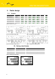
ROUTER DESCRIPTION 5. Router design 5.1. Version Box UR5i v2B set SIM1 SIM2 I/O USB PORT1 PORT2 Plastic UR5i v2B SL set Metal UR5i v2F set Plastic UR5i v2F SL set Metal Table 2: Router version Fig. 2: Front panel UR5i v2B Fig. 3: Front panel UR5i v2B SL Fig. 4: Front panel UR5i v2F SL Fig. 5: Front panel UR5i v2F SL 5.2.
ROUTER DESCRIPTION Fig. 8: Label UR5i v2F Fig. 9: Label UR5i v2F SL 5.3. Ordering code 5.3.1. Basic version Expansion port Ordering code Version without expansion port UR5i v2B set Version with expansion Ethernet port UR5i v2B set ETH Version with expansion RS232 port UR5i v2B set RS232 Version with expansion RS485 port UR5i v2B set RS458 Version with expansion MBUS port UR5i v2B set MBUS Version with expansion CNT port UR5i v2B set CNT Table 4: Ordering code of basic version 5.3.2.
ROUTER DESCRIPTION 5.4. Basic dimensions plastic box Fig. 10 Basic dimensions plastic box 5.5. Basic dimensions metal box Fig.
ROUTER DESCRIPTION 5.6. Mechanical external dimensions and mounting recommendations Mounting recommendations: • possibility to be put on a work surface, • DIN rail with clips CPD2 (Elpac clip SL for SL version) are included. For the most of applications with a built-in router in a switch board it is possible to recognize two kinds of environments: • • no public and industry environment of low voltage with high interference, public environment of low voltage without high interference.
ROUTER DESCRIPTION • for every cables we recommend to bind the bunch according to the following picture, we recommend for this use: length of the bunch (combination of power supply and data cables) can be maximum 1,5 m, if the length of data cables exceeds 1,5 m or in the event of, the cable leads towards the switch - board, we recommend installing over - voltage protectors (surge suppressors), with data cables they mustn't carry cables with reticular tension ~ 230 V/50 Hz, all signals to sensors mus
ROUTER DESCRIPTION 5.7. User interfaces (connectors) On the front panel is located: Label Connector Description PWR 2-pin Connector for connection the power supply adapter. ETH RJ45 Connector for connection into the local computer network. PORT1 RJ45 PORT2 RJ45 ANT SMA Connector for connection main antenna. AUX SMA Connector for connection diversity antenna. USB USB-A Host I/O 3-pin SIM1 - Holder for first SIM card. SIM2 - Holder for second SIM card (only FULL version).
ROUTER DESCRIPTION 5.7.1. Status indication About router status inform eight led indicators on the front panel and on every port are two LED indicators, which inform about port status.
ROUTER DESCRIPTION 5.7.2. Power connector PWR Panel socket 2-pin. Pin number 1 2 Signal mark VCC (+) GND (-) Description Positive pole of DC supply voltage (+10 to +30 VDC) Negative pole of DC supply voltage Table 8: Connection of power connector Fig. 20: Power connector Power supply for router is required between +10 V to +30 V DC supply. Protection against reversed polarity without signaling is built into the router. The power consumption during receiving is 1W.
ROUTER DESCRIPTION 5.7.3. Antenna connector ANT and AUX The antenna is connected to the router using the SMA connector on the front panel. The router can not operate without the main antenna connected labeled as ANT. ANT connector used to connect the main antenna router. To connect the second antenna for diversity income is used second connector AUX. Example of antenna: Fig. 23: External antenna The antenna with the SMA connector.
ROUTER DESCRIPTION 5.7.4. SIM card reader The SIM card reader for 3 V and 1.8 V SIM cards is located on the front panel of the router. To initiate the router into operation it is necessary to insert an activated SIM card with unblocked PIN in the reader. The SIM cards might be of different adjusted APN (Access Point Name). Changing the SIM card: Press the small yellow button to eject the reader holder. Insert the SIM card into the reader holder and slide it in the reader. (See bellow picture) Fig.
ROUTER DESCRIPTION Ethernet cable plug into the RJ45 connector labeled as ETH. (See bellow picture) Fig. 27: Connection Ethernet cable The ETH router connection: Fig.
ROUTER DESCRIPTION 5.7.6. PORT1 The PORT1 is equipped with one of the offered options ports. For PORT1 are available on the interface. PORT1 RS232, RS485/422, ETHERNET, M-BUS, CNT Description, connection and examples of expansion connection ports can be found in separate manuals expansion ports. PORT1 cable plug into the RJ45 connector labeled as ETH. (See bellow picture) Fig. 29: Connection PORT1 cable 5.7.7. PORT2 The PORT2 is equipped with one of the offered options ports.
ROUTER DESCRIPTION 5.7.8. USB port Panel socket USB-A. Pin Signal mark number 1 +5V 2 USB data 3 USB data + 4 GND Description Positive pole of 5V DC supply voltage USB data signal – negative pole USB data signal – positive pole Negative pole of DC supply voltage Table 10: Connection of USB connector Fig. 31: USB connector Example of connecting devices with serial interface to the USB router: Fig. 32: Connection PLC to the router Example of connecting of USB flash disk to the USB router: Fig.
ROUTER DESCRIPTION 5.7.9. I/O port Panel socket 3pin. Pin no. Signal mark 1 2 3 BIN0 GND OUT0 Description Binary input Signal ground Binary output Data flow direction Input Output Table 11: Connection of I/O port Fig. 34: I/O connector The user interface I/O is for processing of binary input signal and to control (settings) of binary output signal. Binary output is not switched to ground in the default configuration. Maximum load binary output is 30V / 100mA.
ROUTER DESCRIPTION 5.7.10. Reset It is important to distinguish between reset and reboot the router. Action Reboot Reset Router behavior Turn off and then turn on router Restore default configuration and to reboot the router. Invoking events Disconnect and connect the power. Press the reboot button in the web configuration. Press RST button.
ROUTER DESCRIPTION 6. First use 6.1. Connecting the router before first use Before you give up the router, it is necessary to connect all components needed for the operation of your applications and the SIM card must be inserted. (See bellow picture) The router can not operate without connected antenna, SIM card and power supply. In operation, the router must be connected to the antenna, otherwise damage to the router. Fig.
ROUTER DESCRIPTION 6.2. Start router The router is set up connecting the power supply to the router. In the default setting the router starts to login automatically to the preset APN. Device on the Ethernet port DHCP server will assign addresses. The behavior of the router can be modified by means of the web or Telnet interface, which is described in the configuration manual. The power consumption during receiving is 1W. The peak power consumption during data sending is 5,5W.
TECHNICAL PARAMETRES 7. Technical parameters 7.1. Technical parameters of router UR5i v2 Complies with standards Temperature range Protection Supply voltage Consumption Function Storage Freely In switch board Reception GPRS UMTS/HSDPA Dimensions Weight Antenna connector User interface ETH USB PORT1 PORT2 EN 301 511, v9.0.2, EN 301 908-1&2, v3.2.1, ETSI EN 301 489-1 V1.8.1, EN 60950-1:06 ed.
TECHNICAL PARAMETERS 7.3. Technical parameters of processor 32b ARM microprocessor Memory 512Mb DDR SDRAM 128Mb FLASH 1Mb MRAM Serial interface RS232 Ethernet interface 10/100Mbit/s USB 2.0 interface Interface Table 15: Technical parameters of processor 7.4. Technical parameters of I/O port Port IO Input/Output Binary input reed contact with trigger level 1,3 up to 1,4 V Binary output 120 mA/max. 30 V Table 16: Technical parameters of I/O port 7.5.
RECOMMENDED LITERATURE 8. Recommended literature [1] Conel: Start guide, [2] Conel: Configuration manual, [3] Conel: User’s manual - Expansion port RS232, [4] Conel: User’s manual - Expansion port RS485/RS422, [5] Conel: User’s manual - Expansion port M-BUS, [6] Conel: User’s manual - Expansion port CNT, [7] Conel: User’s manual - Expansion port ETH, [8] Conel: Application guide – Expansion port mounting, [9] Conel: Application guide – Programmer guide. 9.
FAQ 10. FAQ ¾ I can’t get from internet on equipment, which is connected to router and I have NAT enabled. The device's gateway has to be configured as the router. ¾ Router resets itself, connection on Ethernet fails. It is necessary to use an antenna, which will be situated far from power supply. ¾ I don’t get on web server at NAT.
FAQ ¾ L2TP or IPSec isn’t establishing. Verify the reason in the log system. ¾ I switched the router to offline mode by the SMS message, but the router is in online mode after restart. Control SMS message doesn’t change the router configuration. If the router is switched to offline mode by the SMS message the router will be in this mode up to next restart. This behaviour is the same for next all control SMS messages.
CUSTOMERS SUPPORT 11. Customers support Up to date information about the product is on website: http://www.conel.cz/ Upkeep-advices: The SIM-card must be handled carefully as with a credit card. Do not bend, do not scratch on this and do not expose to static electricity. During cleaning of the router do not use aggressive chemicals, solvents and abrasive cleaners! Conel Company hereby declares that the router narrated in this user’s guide fits all basic demands of directive 1999/5/EC (R&TTE).