Installation Manual Conergy TS Open and Closed Systems www.conergy.com.
Table of Contents 1 Installer Information 2 1.1 The environmental benefits 2 1.2 Why Conergy? 2 1.3 How does the system work? 2 1.4 Conergy TS model number explained 4 1.5 Important safety information 5 1.6 If the customer is away for a period of time 5 1.7 Water discharge through the pressure valve 5 Troubleshooting 6 2 2.1 Low solar energy input 6 2.2 Solar collector shading 6 2.3 Booster system not operating 6 2.4 Excessive water discharge from the valves? 6 2.
1 Installation Information ENGLISH 1 Installation Information You are installing one of the most advanced solar water heaters in the world. This manual provides you with the essential information needed to install the Conergy Thermosiphon System correctly. Please read it carefully and follow all the instructions. We hope you find the following information useful. 1.1 The environmental benefits A Conergy solar water heater is an excellent and economic energy solution.
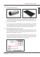
1 Installation Information Storage Tank & Solar Collectors ENGLISH 1.3.1 Conergy TS 300 litre vitreous enamel tank LC collector The potable water storage tank is used to store the heated water ready for household use. It is constructed using high quality vitreous enamel lined low carbon steel to provide long life. The tank is insulated with a high density polyurethane material to ensure minimal heat losses and maximmum structural strength.
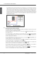
1 Installation Information ENGLISH For gas AES systems the electric element in the storage tank is not connected to an electricity supply. Instead a continuous flow gas water heater is fitted adjacent to the storage tank and in series with the hot water supply from the storage tank and the household hot water pipe system. As the hot water from the solar storage tank passes through the gas heater its temperature is automatically monitored.
1 Installation Information Important safety information | All water heaters have the ability to produce hot water very quickly. To reduce the risk of scald injury it is recommended that a temperature control valve be fitted to the hot water supply pipe work. This valve should be checked at regular intervals to ensure its operation and settings remain correct. Please check that the pressure & temperature relief valve relief pipe is not located where it can cause damage if hot water is discharged.
2 Troubleshooting ENGLISH 2 Troubleshooting What to check for during service calls If there is not enough hot water we recommend that the following points are considered as part of the service call. The most obvious reasons for a lack of hot water could be one of the following: 2.
3 System Maintenance System Maintenance The Conergy system is designed such that there is little to do regarding system maintenance. Should you decide that you want to inspect the roof mounted system it is essential that you use all safety devices required to ensure your personal safety.
4 Installation Instructions ENGLISH 4 Installation Instructions Important Notes | DO NOT commence an installation until you have satisfied yourself that all safety issues associated with working on and lifting components onto a roof have been addressed. | All work associated with the installation must comply with local authority regulations including AS/NZS 3500.4.2. Where these installation instructions and local regulations are in conflict, local regulations must prevail. 4.
4 Installation Instructions Connection and mounting part kits ENGLISH 4.3 The table below indicates the connection and mounting kits required for each model system: 4.
4 Installation Instructions ENGLISH | 4.5 The roof system must be carefully inspected to ensure it can support the systems weight once it is filled with water. Particular care must be taken where the front foot of the storage tank is located. Typically the tank front foot should be located over a tile batten, purlin or similar for maximum strength. If the roof can not support the load, additional bracing must be installed before the solar water heater is installed.
4 Installation Instructions System Installation Please note that the detail letters referred to in the installation text refer to the diagrams on page 12 and onwards. 1. Place one end of the bottom collector mounting rail (Detail E) at the location marked before (refer to point 2) and lay horizontally across the roof to the left. 2. Locate two roof trusses which are under the collector mounting rail (as near as possible to the outer edges of the rail).
4 Installation Instructions ENGLISH 18. For closed circuit models insert the 100 kPa closed circuit pressure relief valve into the ½” tank socket as shown in Detail A. Note this valve is not used on open circuit models. 19. Using the straps supplied with the Parts Kit place one into each side of the tank front foot as shown in Detail A. back leg so that they are over a rafter then screw fix in place to the rafter to secure the tank in place. Take the straps under the tank and screw fix to the roof rafter.
4 Installation Instructions ENGLISH * Components of model TS300/4/O/XX/X/F20LC Item No. Part No.
4 Installation Instructions * * Models TS300/4/O/XX/X/E20BC, TS300/4/O/XX/X/E20SB ENGLISH 4.8.2 Components * * Represents all AES and tank options.
4 Installation Instructions 4.8.3 Part No.
4 Installation Instructions ENGLISH * * Components of model TS300/4/C/XX/X/E20BC, TS300/4/C/XX/X/E20SB Item No. Part No.
4 Installation Instructions * Model TS180/2/O/XX/X/F20LC ENGLISH 4.8.4 * Components * Represents all AES and tank options.
ENGLISH 4 Installation Instructions 4.8.5 Item No. Part No.
4 Installation Instructions ENGLISH * * Components of model TS180/3/O/XX/X/E20BC, TS180/3/O/XX/X/E20SB Item No. Part No.
4 Installation Instructions * * Models TS180/3/C/XX/X/E20BC, TS180/2/C/XX/X/E20SB ENGLISH 4.8.6 Components * * Represents all AES and tank options.
4 Installation Instructions 4.9 4.9.1 Part No.
4 Installation Instructions ENGLISH 4.9.4 Pressure & temperature relief valve (P&T valve) Remember this valve can discharge very hot water, so carefully consider its location. Never discharge onto a solid surface like concrete. 1. Fit the 850 kPa/95°C (10 kW) pressure & temperature relief valve supplied in the parts box into the ½” brass tank socket adjacent to the hot outlet tube as shown in (Detail A). 2.
4 Installation Instructions 4.11 Draining the storage tank ENGLISH To drain the water from the storage tank the following procedure is to be followed: 1. Turn off and isolate the power supply to the electrical element. 2. Turn off the water supply to the water heater. 3. Release excess pressure from the tank by manually opening the pressure & temperature relief valve. 4. Disconnect the cold water supply pipe connection to the tank. 5. Fit a ½” flexible drain pipe to the cold connection at the tank.
4 Installation Instructions ENGLISH 4.12.1 Fill and test information and procedure | Cover Collectors for this procedure to prevent pressure variation due to thermal activity in the collectors. | The solar transfer fluid is of food grade and non toxic. However, care must be taken when handling not to spill or accidentally consume. Always use the solar transfer fluid as specified by Conergy and outlined above.
4 Installation Instructions ENGLISH 5. Using a bicycle pump or similar connected to the jacket relief valve, as shown to the right, pressurise the system to 120 kPa. 6. Check all fittings for signs of leakage and tighten if required. 7. Check over a 10 minute period that the pressure on the test gauge remains unchanged. 8.
4 Installation Instructions Electrical Circuit Diagram ENGLISH 4.13.2 /)# ,)6% , #9#,).' 4(%2-/34!4 %,%-%.4 4.13.3 4.14 .%542!, . %!24( % Electrical Connection for Gas AES Systems For models using a gas AES system the electrician is required to install a domestic electrical outlet socket adjacent to the gas heater location. The gas heater requires a 220-240 volt 50 Hz powersupply and is rated at 0.47 amperes. Gas (AES) Installation Instructions Note Important note: 4.14.
5 Commissioning & Customer Hand Over Commissioning & Customer Hand Over When all connections have been completed the solar water heater can be filled with water. | Before turning on the cold water supply open one hot tap within the household to release air from the system during the filling process. Do not leave the open tap unattended during the filling process. | Turn on the cold water supply and wait for the system to fill.
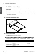
6 ANNEX - Mounting frame for flat roof ANNEX - Mounting frame for flat roof ENGLISH 6 2BC = 2000mm 2B = 2000mm 2S = 2000mm 2SP = 2000mm 2LC = 1935mm Tank E D 800 C A B 2660 1500 Note: 1. Ensure tank is located directly over vertical support.
Item No. Article Description No. PK-1014 Qty PK-2055, PK-2056, PK-2057 Qty.
55-4008-REV1-0708 For further technical information, please contact your Conergy state manager Conergy Pty Ltd Unit 6 44-48 O’Dea Avenue Waterloo NSW 2017 Ph: 02 8507 2222 Email: solarhotwater@conergy.com.au www.conergy.com.