
Instructions

4: Configuration Using Web Manager
DeviceLinx™ XPort/XChip SoC User Guide 35
sent to the recipient(s) when a single trigger event remains
active.
3. When you are finished, click the OK button.
4. On the main menu, click Apply Settings.
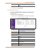
Configurable Pin Settings
There are three configurable hardware pins on the XPort unit. For each pin, configure
the pin function, communication direction, and activity level. For more information,
see 9:GPIO Interface.
To configure the XPort’s Configurable Pins:
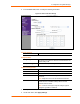
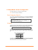
1. On the main menu, click Configurable Pins. The Configurable Pins page opens.
Figure 4-11. Configurable Pins Settings
2. Configure or modify the following fields for each pin:
Function
From the drop-down menu, select the purpose of the specified
pin. See Configurable Pin Functions (below) for a description
of each available function.
Direction
Select whether the pin inputs or outputs.
Active Level Select the signal active level (Low or High).
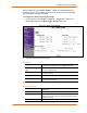
Configurable Pin Functions
General Purpose I/O
Monitors input using the 77F0 port or controls output by the
77F0 port.
Modem Ctrl In (DTR)
Allows for control of the connection (and disconnection) of
channel 1.
Modem Ctrl Out (DCD)
Indicates a connection is established on channel 1.
Link Status
Indicates the Ethernet link state.
Status LED 1
Indicates channel 1 status and extended diagnostics when
status LED 3 is lit.
Status LED 3
Indicates errors and configurations.
HW Flow Control In
(RTS)
Allows for flow control on the connection with hardware
handshaking.