
Service manual

57
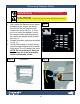
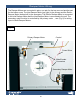
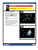
Damper Motor Installation
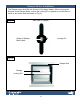
Fig. 9
Side view of Damper
Locking Pin
Shape of Damper
Motor Shaft
The Damper motor shaft ts into the end of the damp blades. When securing the
Damper to the Damper Motor, ensure the Locking Pin is against one of the at sur-
faces on the motor shaft as shown in (Fig. 9).
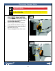
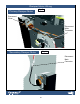
Fig. 10
Damper Box
Damper
Locking Pin