
Specifications

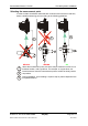
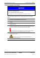
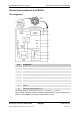
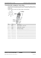
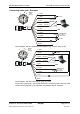
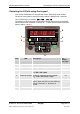
Table Of Contents
- Imprint
- Documentation Representative
- © HYDAC FILTER SYSTEMS GMBH
- Contents
- Preface
- Safety information
- Storing the CS
- Decoding the model code label
- Checking the scope of delivery
- CS1000 Features
- CS1000 Restrictions on use
- CS1x1x dimensions (without display)
- CS1x2x dimensions (with display)
- Hydraulic connection types
- Fastening / mounting the CS1000
- Display rotatable/Adjustable As Needed
- CS1000 hydraulic installation
- Electrical connection of the CS1000
- Setting the measuring mode
- Operating the CS1x2x using the keypad
- Overview of menu structure
- Using switching output
- Setting limit values
- Reading the analog output
- Status Messages
- Connecting CSI-D-5 (Condition Sensor Interface)
- Connecting the CS1000 to an RS-485 bus
- Communicating with the CS1000 via the RS-485 bus
- Taking the CS1000 out of operation
- Disposing of CS1000
- Spare Parts and Accessories
- Cleanliness classes - brief overview
- Checking/resetting default settings
- Technical data
- Recalibration
- Customer Service
- Model Code
- EC declaration of conformity
ContaminationSensor CS 1000 CS1000 hydraulic installation
HYDAC FILTER SYSTEMS GMBH
en(us)
Page 24/112
BeWa CS1000 3764916 300 en-us 2012-08-29.doc 2012-08-29
Hydraulic connection of the CS1000
NOTICE
Excessive operating pressure
The ContaminationSensor will be destroyed.
► Observe the maximum operating pressure of 350 bar / 5075 psi.
Observe the following sequence when connecting the sensor to the hydraulic
system:
1. Connect the return line to the outlet of the CS. G1/4 ISO 228 threaded
connection, recommended diameter of line ≥ 4 mm.
2. Then connect the other end of the return line to the system tank, for
example.
3. Check the pressure at the measurement location. Note the maximum
operating pressure.
4. Connect the measurement line to the inlet of the CS.
G1/4 ISO 228 threaded connection. We recommend an internal Ø ≤ 4mm
for the line in order to prevent particle deposits (sedimentation).
If particles ≥ 400 µm are anticipated in the hydraulic system, install a
strainer upstream from the ContaminationSensor. (e.g. CM-S).
5. Connect the other end of the measurement line to the measurement point
on the hydraulic system.
Oil begins to flow as soon as the ContaminationSensor is
connected with the pressure line.
6. The hydraulic connection is complete.