
Specifications

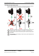
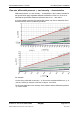
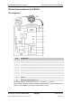
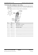
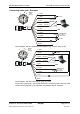
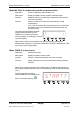
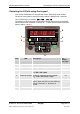
Table Of Contents
- Imprint
- Documentation Representative
- © HYDAC FILTER SYSTEMS GMBH
- Contents
- Preface
- Safety information
- Storing the CS
- Decoding the model code label
- Checking the scope of delivery
- CS1000 Features
- CS1000 Restrictions on use
- CS1x1x dimensions (without display)
- CS1x2x dimensions (with display)
- Hydraulic connection types
- Fastening / mounting the CS1000
- Display rotatable/Adjustable As Needed
- CS1000 hydraulic installation
- Electrical connection of the CS1000
- Setting the measuring mode
- Operating the CS1x2x using the keypad
- Overview of menu structure
- Using switching output
- Setting limit values
- Reading the analog output
- Status Messages
- Connecting CSI-D-5 (Condition Sensor Interface)
- Connecting the CS1000 to an RS-485 bus
- Communicating with the CS1000 via the RS-485 bus
- Taking the CS1000 out of operation
- Disposing of CS1000
- Spare Parts and Accessories
- Cleanliness classes - brief overview
- Checking/resetting default settings
- Technical data
- Recalibration
- Customer Service
- Model Code
- EC declaration of conformity
ContaminationSensor CS 1000 Operating the CS1x2x using the keypad
HYDAC FILTER SYSTEMS GMBH
en(us)
Page 30/112
BeWa CS1000 3764916 300 en-us 2012-08-29.doc 2012-08-29
Operating the CS1x2x using the keypad
If the sensor is switched on or supplied with power, the display shows HYDAC
CS1000 in moving letters, then the firmware version is displayed for 2 seconds.
This is followed by a countdown:
WAIT99 … WAIT0.
The duration of the countdown corresponds to the set measurement time MTIME.
This means that the countdown runs from 99 ... 0 within the set measurement time
(factory setting = 60 sec).
B
D
F
E
A
C
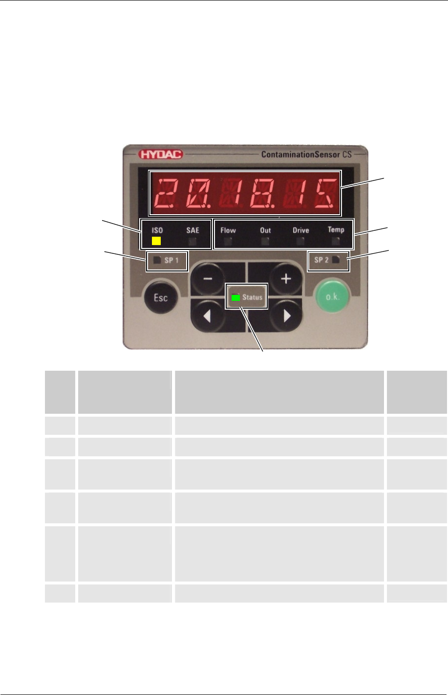
Item LED Description For
details,
see page
A Status Status display
86
B Display 6-figure display with 17 segments each
86
C Measured variable Display of respective measured variable,
e.g: ISO / SAE / NAS
32
D Additional variable Display of respective service variable,
e.g.: Flow / Out / Drive / Temp
33
E Switch point 1 Indicates the status of the switching
output. When the LED is lit, the switching
output is activated, i.e. the switch is
closed.
52
F Switch point 2 Reserved