
Specifications

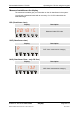
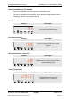
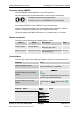
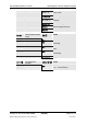

Table Of Contents
- Imprint
- Documentation Representative
- © HYDAC FILTER SYSTEMS GMBH
- Contents
- Preface
- Safety information
- Storing the CS
- Decoding the model code label
- Checking the scope of delivery
- CS1000 Features
- CS1000 Restrictions on use
- CS1x1x dimensions (without display)
- CS1x2x dimensions (with display)
- Hydraulic connection types
- Fastening / mounting the CS1000
- Display rotatable/Adjustable As Needed
- CS1000 hydraulic installation
- Electrical connection of the CS1000
- Setting the measuring mode
- Operating the CS1x2x using the keypad
- Overview of menu structure
- Using switching output
- Setting limit values
- Reading the analog output
- Status Messages
- Connecting CSI-D-5 (Condition Sensor Interface)
- Connecting the CS1000 to an RS-485 bus
- Communicating with the CS1000 via the RS-485 bus
- Taking the CS1000 out of operation
- Disposing of CS1000
- Spare Parts and Accessories
- Cleanliness classes - brief overview
- Checking/resetting default settings
- Technical data
- Recalibration
- Customer Service
- Model Code
- EC declaration of conformity
ContaminationSensor CS 1000 Operating the CS1x2x using the keypad
HYDAC FILTER SYSTEMS GMBH
en(us)
Page 33/112
BeWa CS1000 3764916 300 en-us 2012-08-29.doc 2012-08-29
Service variables on the display
The service variables inform you about the current status in the
ContaminationSensor.
The service variables are not calibrated. They represent an approximate value for
installing the sensor in the hydraulic system.
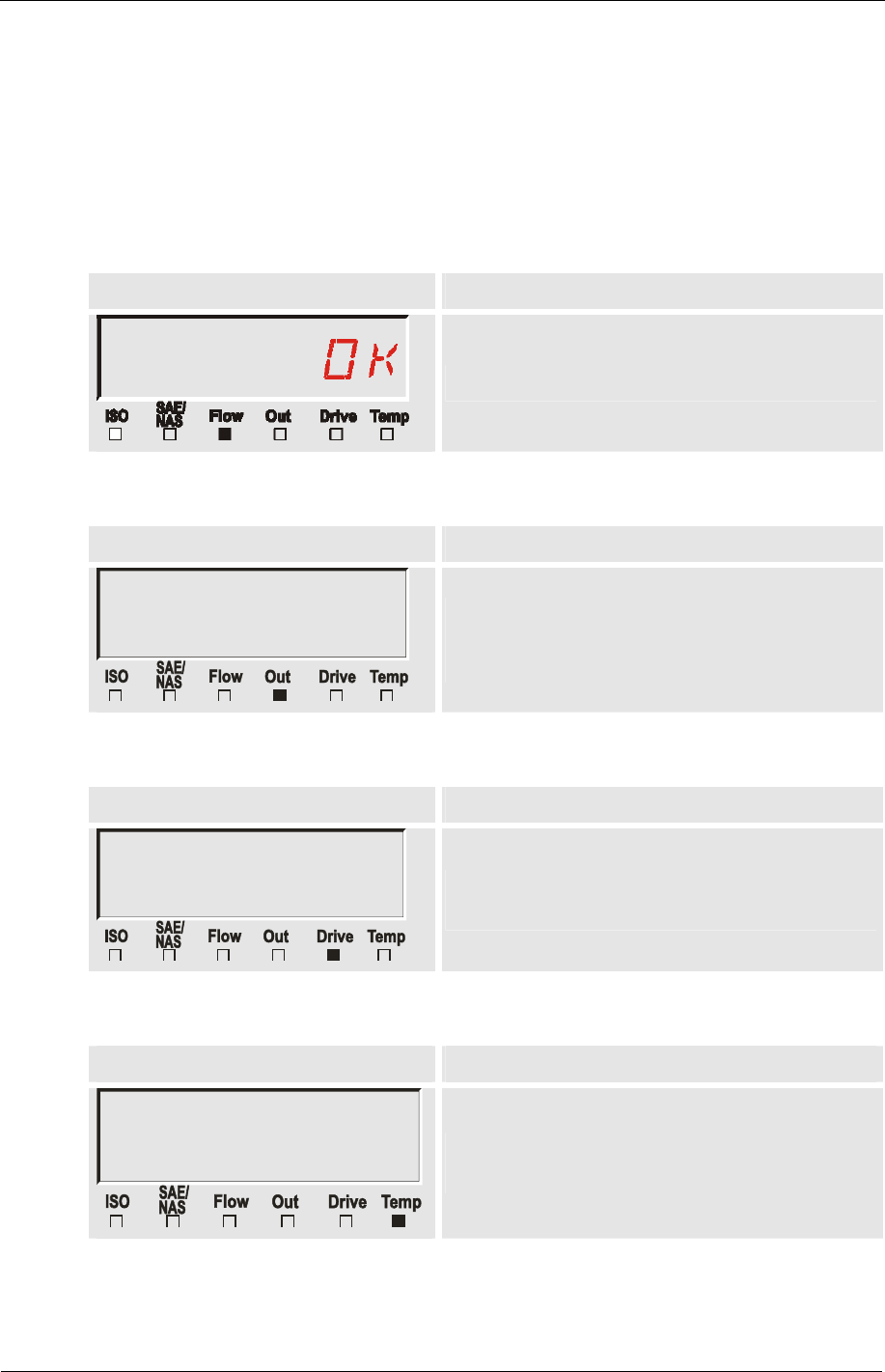
Flow (flow rate)
Display Description
Flow rate in permissible range
Out (Analog output)
Display Description
1§8
Current or voltage output at the analog
output.
(example: 13.8 mA)
Drive (performance of the LED)
Display Description
60
Performance (1-100%) of the LED in the
sensor.(example: 60%)
Temp (Temperature)
Display Description
2)5C
Fluid temperature in the sensor.
(example: 29.5 °C or 84.2 °F)