INSTALLATION AND OPERATING INSTRUCTIONS CS/CSM SERIES RESIDENTIAL WATER SOFTENERS MODELS: CS1001 CS1501 CS2001 CSM1001 CSM1501 CSM2001 Installer, please leave with homeowner. Homeowner, retain for future reference.
SAFETY INFORMATION Read, understand, and follow all safety information contained in these instructions prior to installation and use of the Aqua-Pure® CS/CSM Series Residential Water Softener. Retain these instructions for future reference. Failure to follow installation, operation and maintenance instructions may result in property damage and will void warranty.
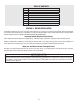
TABLE OF CONTENTS SECTION DESCRIPTION 1 BEFORE INSTALLATION 2 INSTALLATION 3 REGENERATION INSTRUCTIONS 4 MAINTENANCE 5 SERVICE INSTRUCTIONS 6 SPECIFICATIONS & OPERATING DATA 7 PARTS 8 LIMITED WARRANTY SECTION 1: BEFORE INSTALLATION Congratulations! We believe your purchase of this water softener will prove to be a very wise choice. When properly installed, operated, and maintained, your new water softener will provide years of dependable service.
Check Your Pumping Rate and Water Pressure: Two water system conditions must be checked carefully to avoid unsatisfactory operation or equipment damage: 1) MINIMUM water pressure required at the water softener inlet is 20 psi (138 kPa). CAUTION To reduce the risk associated with property damage due to water leakage: • Do not install if water pressure exceeds 125 psi. If your water pressure exceeds 80 psi (552 kPa), you must install a pressure limiting valve.
Facts to Remember While Planning The Installation: 1) All installation procedures MUST conform to local and state plumbing codes. 2) If lawn sprinklers, a swimming pool, or geothermal heating/cooling or water for other devices/activities are to be treated by the water softener, a larger model MUST be selected to accommodate the higher flow rate plus the backwashing requirements of the water softener.
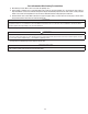
SECTION 2: INSTALLATION TREATED WATER WASTE DRAIN WASTE DRAIN TREATED SOFT WATER PRESSURE TANK BRINE TANK RAW WELL WATER WATER SOFTENER BACKWASH FILTER PRESSURE SWITCH. CHECK VALVE TYPICAL WELL INSTALLATION TREATED WATER TREATED SOFT WATER WASTE DRAIN WASTE DRAIN WATER FOR LAWN SPRINKLERS OR OTHER HIGH DEMAND METER BRINE TANK RAW WATER WATER SOFTENER BACKWASH FILTER CHECK VALVE TYPICAL PUBLIC WATER SUPPLY INSTALLATION Figure 1.
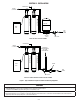
Step 1 If not factory pre-installed, attach bypass valve or yoke assembly using adapter couplings, clips and screws to control valve (Figure 2). On meter initiated models, attach meter between bypass valve and control valve (Figure 2). Figure 2. Softener And Brine Tank Assembly, Top View Step 2 Shut off all water at main supply valve. On a private well system, turn off power to pump and drain pressure tank. Make certain pressure is relieved from complete system by opening nearest faucet to drain system.
Step 5 Attach drain line to drain line fitting. To prevent back pressure from reducing flow rate below minimum required for backwash, drain line must be sized according to run length and relative height. Be careful not to bend flexible drain tubing sharply enough to cause "kinking" (if kinking occurs drain line must be replaced). Typical examples of proper drain line diameters are: EQUIPMENT DRAIN LINE AIR GAP 2" REF. (1) 1/2 in. ID up to 15 ft. when discharge is lower than inlet. DRAIN (2) 5/8 in.
Step 13 Set time of day (refer to appropriate How To Set Time Clock/Meter Regeneration Control, Section 3). When shifting to daylight saving time (and back), you may wish to adjust time of day accordingly. NOTE: time of regeneration is preset for 2:00 a.m. because at this time water consumption is generally minimal (a built-in hard water bypass does, however, permit water to be drawn during regeneration). Should your life style require regular use of water during the 2:00 to 3:00 a.m.
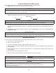
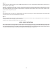
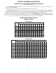
SECTION 3: REGENERATION INSTRUCTIONS INSTRUCTIONS FOR USING REGENERATION FREQUENCY SCHEDULES: (Time clock initiated models only) 1) Determine ADJUSTED HARDNESS by adding three (3) times the iron content in parts per million (ppm) to the hardness in grains per gallon (gpg). The resulting number is ADJUSTED HARDNESS. EXAMPLE: Hardness is 14 gpg and iron is 2 ppm. ADJUSTED HARDNESS is 20 gpg (14 plus 3 times 2). 2) Select REGENERATION FREQUENCY SCHEDULE corresponding to your model.
REGENERATION FREQUENCY SCHEDULES (Cont'd) (TIMES PER 12 DAYS) Model CS2001 Persons in Family Hardness -- GPG 5 10 15 20 25 30 35 40 45 50 55 60 65 70 75 80 85 90 1 1 1 1 1 1 1 `1 1 1 1 1 2 2 2 2 2 2 2 2 1 1 1 1 1 2 1 2 2 2 2 3 3 3 3 3 3 4 3 1 1 1 2 2 2 2 3 3 3 3 4 4 4 4 6 6 6 4 1 1 2 2 2 3 2 3 4 4 4 6 6 6 6 6 6 12 5 1 1 2 2 3 3 3 4 4 6 6 6 6 12 12 12 12 12 6 1 2 2 3 3 4 3 6 6 6 6 12
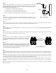
HOW TO SET TIME CLOCK REGENERATION CONTROL Above time clock shown in the SERVICE POSITION with dot opposite TIME OF DAY ARROW. HOW TO SET DAYS ON WHICH WATER SOFTENER IS TO REGENERATE: Rotate the skipper wheel until the number "1" is at the red pointer. Set the days that regeneration is to occur by sliding tabs on the skipper wheel outward to expose trip fingers. Each tab is one day. Finger at red pointer is tonight.
HOW TO SET REGENERATION CYCLE PROGRAM The regeneration cycle program on your water softener has been factory preset, however, portions of the cycle or program may be lengthened or shortened in time to suit local conditions. To expose cycle program wheel, grasp time clock in upper left-hand corner and pull, releasing snap retainer and swinging time clock to the right. To change the regeneration cycle program, the program wheel must be removed.
HOW TO SET METER REGENERATION CONTROL TYPICAL RESIDENTIAL APPLICATION: To program, just set the time, set the hardness and it automatically monitors system needs and regenerates only when necessary. To set time of day press red time set button and turn 24-hour gear until present time of day is opposite "time of day arrow.
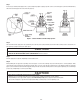
SECTION 4: MAINTENANCE REPLENISHMENT OF SALT SUPPLY: The salt storage capacity of the brine tank is approximately 160 lbs (72.6 kg). During each regeneration a specific amount of salt is consumed, thus requiring its periodic replenishment (the frequency is dependent on the regeneration schedule). Always replenish salt before the supply is exhausted to assure a continuous supply of softened water. TYPE OF SALT TO USE: Any type of water softener salt may be used.
SECTION 5: SERVICE INSTRUCTIONS PROBLEM 1 2 3 Hard water, (unit not using salt; liquid level in brine tank not too high). Hard water, (unit using salt; liquid level in brine tank NOT too high). Liquid level in brine tank TOO high. POSSIBLE CAUSE SOLUTION A. Electrical service to unit interrupted. A. Assure permanent electrical service (check fuse, plug, pull chain or switch). B. Time clock not working. B. Replace time clock motor. C. Time clock improperly set. C.
SECTION 6: SPECIFICATIONS AND OPERATING DATA ITEM Time Clock Metered CS1001 CS1501 CS2001 CSM1001 CSM1501 CSM2001 Nominal Media Volume, cu. ft. (cu. mtr.) 1.0 (0.03) 1.5 (0.04) 2.0 (0.06) Salt Dose, lbs. (kg) Factory Setting Maximum Setting 6 (2.7) 15.0 (6.8) 9 (4.1) 24 (10.9) 12 (5.4) 24 (10.9) Softening Capacity, grains (1) At Factory Salt Setting At Maximum Salt Setting 18,600 30,000 27,900 45,000 37,200 54,000 Flow Rate, gpm (lpm) (2) Service (10 min. or less) 7.5 (28.45) 9.
SECTION 7: PARTS COMPONENT PARTS LIST TWO TANK MODELS (CS & CSM SERIES) REF NO. 1 DESCRIPTION CS1001 CSM1001 CS1501 CSM1501 CS2001 CSM2001 Control Valve, Time Clock Initiation, with Cover, less Bypass (CS Series) C100150-5W3-2N1 C100240-5W3-2N1 C100240-5W3-2N1 Control Valve, Meter Initiation, with Cover, less Bypass (CSM Series) C12J150-5W3-2N1 C12N240-5W3-2N1 C12R240-5W3-2N1 52-87001 52-87001 52-87001 10381 10381 10381 2 Adapter Assy., Threaded-CEC (Incl. Ref.
CEC 1000 SERIES SOFTENER CONTROL - 12 DAY TIME CLOCK 7-3
ONLY THOSE PARTS CIRCLED IN DRAWING AND/OR LISTED BELOW ARE STOCK ITEMS ALL OTHERS ARE SPECIAL ORDER, NON-RETURNABLE PARTS LIST - 12 DAY TIME CLOCK REF. PART NO.
CEC 1000 SERIES SOFTENER CONTROL - METER INITIATED 7-4
ONLY THOSE PARTS CIRCLED IN DRAWING AND/OR LISTED BELOW ARE STOCK ITEMS ALL OTHERS ARE SPECIAL ORDER, NON-RETURNABLE METER INITIATED PARTS LIST REF. PART NO.
WIRING DIAGRAM FOR VALVE DRIVE MOTOR AND Time clock CEC 1000 SERIES VALVES TIMER MOTOR BL AC K VALVE MOTOR BL AC K PROGRAM WHEEL PROGRAM RE-SET SWITCH DRIVE CAM SWITCH BLACK RAPID RINSE SERVICE CAM RED BLUE SERVICE CAM SWITCH BRINE TANK FILL RAPID RINSE BRINE AND RINSE GREEN BACKWASH BLACK RED YELLOW BRINE & RINSE BROWN BROWN DRIVE CAM BACKWASH YELLOW SERVICE BLACK BLACK BLACK WHITE BLUE WHITE PLUG-120 V.-A.C.
SECTION 8: LIMITED WARRANTY Limited Warranty: 3M Purification Inc. warrants this Product to be free from defects in material and workmanship during normal use for the warranty period set forth below. The warranty period commences from the date of purchase. This warranty does not cover failures resulting from abuse, misuse, alteration or damage not caused by 3M Purification Inc. or failure to follow installation and use instructions.