CCD B/W CAMERA CS4000 SERIES OPERATION MANUAL For Customer Use: Enter below the Serial No. which is located on the rear panel of the camera control unit. Retain this information for future reference, Model name. Serial No. TOKYO ELECTRONIC INDUSTRY CO.,LTD.
1. FEATURES (1) (2) (3) (4) Compact and light weight camera head. Equipped with AGC (Automatic Gain Control) which allows wide dynamic range from bright to dark subjects. Equipped with RTS (Random Trigger Shutter) which allows free timing capture with stable SYNC. Available external SYNC (HD/VD, YS, SYNC) operation. 2. PRECAUTION (1) (2) (3) (4) (5) (6) (7) (8) (9) (10) This equipment should be used with DC12V only. To prevent electric shocks and fire hazards, do not use any other power source.
. NAMING OF THIES PRODUCTS (Example) CS 4 3 1 0 V -01 Length of the camera cable (Only for square type camera head) 02: 2m 03: 3m 05: 5m Direction of the camera cable (Only for square type camera head) (From rear sight) Z: UP X: DOWN W: LEFT Y: RIGHT V: BACKWARD "0" fixed Appearance of the camera head or lens mount 0: Round type 1: Square type 2: C-mount type 3: Square C-mount type Size of CCD 2: 1/2 inches 3: 1/3 inches "4"fixed Trade mark CS : camera system CSH : camera head CSU : camera control u
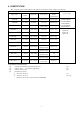
. CONSTITUTION The constitution (the combinations of the camera head and the camera cable) is as following. Camera head Appearance Camera cable Size of the Type name Appearance Lens mount of the CCD camera head 2m: (CPRC4000-02) M15.5 P0.5 CSH4200 1/2 inches Ø 17mm Round type (CPRC4100-02) (male screw) 3m: (CPRC4000-03) CSH4220 1/2 inches Ø 29mm C-mount Round type (CPC4100-03) 5m: (CPRC4000-05) M10.5 P0.
. OPTIONAL ACCESSORIES Purchase the following optional accessories depending on your system as necessary. (1) Cable for power supply (2) Connector for power input (3) Camera lead mounting kit (4) C-mount adapter (5) Lens Focal length & Aperture (Iris) f=4 mm, F 2.2 f=7.5 mm, F 1.6 f=15 mm, F 2.0 f=24 mm, F 3.
. CONNECTIONS When install the CS4000 series camera to your system, you have to connect between equipment.
(2) Rear panel of the camera control unit ① [CAMERA] connector This connector is used to connect the camera head and the camera control unit with the camera cable. When insert the connector, please confirm the position of the guide and screw up tightly. If it is loose, it may cause some noise. ② [SYNC OUT] connector (1) Pulse outputs Use them when other equipment required pulses (HD, VD, and SYNC) to be synchronized with the camera.
③ [DC IN / VIDEO OUT] connector (1) DC12V input Connect pin number 2 and / or 11 for DC12V (HOT) and pin number 1 and / or 10 for GND. (2) Video output Composite EIA video output (VS) is output from pin number 4(HOT) and pin number 3(GND). (3) Input pulses for external sync When required external sync-operation between other equipment, use either one of pulse for HD/VD, VS or SYNC. And input HD pulse form pin number 6-5 (GND) and VD from pin number 7-8 (GND) for HD / VD external sync-operation.
(3) How to fix a lens to this camera head To prevent loosing of the lens from the camera head because of some vibration or shock, fix the lens to this camera head with screw tightly. The screw is provided with this camera head.
7. CONTROLS AND ADJUSTMENTS Get to know the name and function of every part of this camera. That way, you can take advantage of every application to take beautiful pictures. (1) Lens * Lens is an optional accessory. ① Iris ring (Aperture ring) for use at manual operation. To reduce aperture, rotate the iris ring toward CLOSE (clockwise). To increase aperture, rotate the iris ring toward OPEN (counterclockwise).
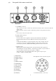
(3) Camera control unit (front panel) ① [POWER] A power on/off switch when power is turned on, the pilot lamp on the power switch will light. ② [SHUTTER] a) Toggle switch . [NOR]: Normal mode. [RDMJ: Random trigger shutter mode. b) Rotary switch This switch is shutter speed selector Shutter speed Normal mode RTS mode [OFF] :off 1/60 sec. [F.L.] :1/100 sec. 1/100 sec. [50/60] :1/60 sec. 1/60 sec. [125] :1/125 sec. 1/125 sec. [2503 :1/250 sec. 1/250 sec. [500] :1/500 sec. 1/500 sec. [1000] :1/1,040 sec.
④[GAMMA] Generally, TV camera provides gamma correction in the video-process amplifiers, which make up apposite side for non linear characteristics of image signals based on CRT’s electron gun in TV receiver and the total performances of the video system have linear (GAMMA: 1.0). Usually, use the gamma correction “ ON “ position, which set the standard camera gamma-value of 0.45. And if required gamma " OFF " (gamma value: 1.0) with the system, turn it to " OFF " position.
8. SUPPLEMENTAL INFORMATIONS (1) Illuminant for better picture (2) Smear When the strong light hits the CCD image sensor, the image of bands in vertical direction tray appear above and under the spot. This is called smear. Especially if the camera shoots under the noon sun or its reflections, a candlelight in the dark, or headlights of cars, these smears may stand out in the picture. The CCD used in the CS4000 series is designed as very strong against the smear.
9. TROUBLE-SHOOTING GUIDE What may initially appear to be trouble is not always a real problem. Make sure first according to the following table before requesting service. Symptoms Check points Power No power is supplied *Have you connected power cord correctly ? Halation or black-out occurs *Check whether the iris ring has accidentally moved out of the normal position.
10. SPECIFICATIONS (1) (2) (3) (4) (5) (6) (7) (8) (9) (10) (11) (12) (13) (14) (15) TV system EIA Image sensor Interline CCD 768(H) x 494(V) ①Active pixel ②Active image area a) 1/2 inches 6.45mm(H) x 4.84mm(V) b) 1/3 inches 4.88mm(H) x 3.66mm(V) Number of scanning lines 525 lines Scanning system 2 : 1 interlace Sync. System Internal / External Scanning frequencies 15.734 kHz ① Horizontal drive 59.
(16) Electronic shutter (17) Random trigger shutter ① Trigger pulse input ② Shutter speed ③ Video signal output field ④ Index pulse output Power source Power consumption Ambient condition ① Temperature ②Humidity Camera cable Dimensions Weight ① Camera head a) CSH4200 b) CSH4220 c) CSH4300 d) CSH4310 e) CSH4400 f) CSH4410 ②Camera control unit a) CSU4000 Emission (18) (19) (20) (21) (22) (23) (24) Shutter speed: 10 position OFF F.
11. MAINTENANCE (1) (2) (3) (4) (5) (6) (7) (8) Cleaning should be done only after units have been disconnected. When the cabinet is dusty, clean by gently wiping with a soft cloth. And avoid the use of strong cleaning agents such as benzene or alcohol as they may damage the cabinet. If malfunctioning occurs, stop using equipment immediately and consult TELI-service shop, the dealer purchased from or qualified personnel.
12. APPEARANCES See page 18~21.
[ CAMERA MOUNTING KIT (OPTION) APPERANCE]
[ CAMERA CONTROL UNIT APPERANCE]
[ CAMERA CABLE (OPTION) APPEARANCE]
CAMERA CABLE (OPTION) APPEARANCE
[ CAMERA HEAD APPERANCE]