Blue Heat/Net Sync User Manual Ethernet-to-Serial Synchronous Communications Connect Tech Inc. 42 Arrow Road Guelph, Ontario N1K 1S6 Tel: Toll: Fax: Email: Web: 519-836-1291 800-426-8979 (North America only) 519-836-4878 sales@connecttech.com support@connecttech.com www.connecttech.com CTIM-00044 Revision 0.
Connect Tech Blue Heat/Net Sync User Manual Limited Lifetime Warranty Connect Tech Inc. provides a Lifetime Warranty for all Connect Tech Inc. products. Should this product, in Connect Tech Inc.'s opinion, fail to be in good working order during the warranty period, Connect Tech Inc. will, at its option, repair or replace this product at no charge, provided that the product has not been subjected to abuse, misuse, accident, disaster or non Connect Tech Inc. authorized modification or repair.
Connect Tech Blue Heat/Net Sync User Manual Customer Support Overview If you experience difficulties after reading the manual and/or using the product, contact the Connect Tech reseller from which you purchased the product. In most cases the reseller can help you with product installation and difficulties. In the event that the reseller is unable to resolve your problem, our highly qualified support staff can assist you.
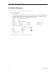
Connect Tech Blue Heat/Net Sync User Manual Certification Statements Preliminary: Testing is still pending. Class A Computing Device Connect Tech Inc. declares that the product(s) covered by the contents of this manual have been tested and found compliant with the below listed standards as required by the Electromagnetic Compatibility (EMC) Directive for General Immunity Compliance.
Connect Tech Blue Heat/Net Sync User Manual Table of Contents Limited Lifetime Warranty ................................................................................................................... 2 Copyright Notice ................................................................................................................................ 2 Trademark Acknowledgment ................................................................................................................
Connect Tech Blue Heat/Net Sync User Manual info .............................................................................................. 27 net ............................................................................................... 27 save ............................................................................................. 29 update.......................................................................................... 29 WCM (Web Configuration Manager) ...........................
Connect Tech Blue Heat/Net Sync User Manual DHCP Setup .................................................................................................. 69 Using SCM ........................................................................................... 69 How the Blue Heat/Net Sync Boots Up ...................................................................... 69 Bootup Sequence ............................................................................................
Connect Tech Blue Heat/Net Sync User Manual List of Tables Table 1: BlueHeat/Net Sync Power Connections and Current Specifications .............................. 16 Table 2: Connector Properties ...................................................................................................... 16 Table 3: Available Special Operations .......................................................................................... 18 Table 4: LED Error Codes for Blue Heat/Net Sync ..............................
Connect Tech Blue Heat/Net Sync User Manual Introduction Connect Tech‟s Blue Heat/Net Sync allows remote access to synchronous/asynchronous serial devices via an Ethernet LAN or the Internet. Blue Heat/Net Sync network-enables serial communication devices that are designed to be connected to serial ports so that the devices no longer need to be tied to a single computer.
Connect Tech Blue Heat/Net Sync User Manual Understanding Virtual COM Ports In a typical serial port setup, the application communicates directly with the connected serial port hardware. Virtual COM ports differ in that the application communicates with a network protocol layer that transfers the necessary information to and from the remote serial ports.
Connect Tech Blue Heat/Net Sync User Manual Hardware Installation Connecting the Blue Heat/Net Sync to Your Network: Before you begin, take a minute to ensure that your package includes the required components for your Blue Heat/Net Sync: • • • • • One Blue Heat/Net Sync unit One power supply One CD containing software and documentation One Phoenix contact screw terminal plug PN: 1847055 One RJ-45 cable (optional) If any of these components is missing, contact Connect Tech or your reseller.
Connect Tech Blue Heat/Net Sync User Manual Serial Port LEDs The serial ports LEDs indicate serial activity for each port. • A flashing LED indicates that the port in question is receiving or transmitting data. Connecting Serial Devices V.28 Connections: V.28 has signaling levels the same EIA RS232. Basic Async (V.28) RS-232 Null Modem Connection This is the typical way to connect a Blue Heat/Net Sync to another serial device.
Connect Tech Blue Heat/Net Sync User Manual RS-422/V.11 Connections The following are basic connections that can be accomplished when the I/O levels are in V.11 (RS422) mode. V.11 mode signaling can be enabled with EIA-530, RS-449 or X.21 modes on your Blue Heat/Net Sync. Blue Heat/Net Sync 2 - TX14 - TX+ 16 - RX+ 3 - RX7 - SR RS-422/V.11 Device RXRX+ TX+ TXSR Figure 5: Basic RS-422/V.11 Asynchronous Connections Blue Heat/Net Sync 2 - TX14 - TX+ 16 - RX+ 3 - RX9 - R/TXC+ 17 - R/TXC7 - SR RS-422/V.
Connect Tech Blue Heat/Net Sync User Manual Loopback Connectors Loopback connectors are useful for performing diagnostics. The following figure illustrates the recommended pinouts for creating loopback connectors for Blue Heat/Net Sync. DB-25 Male 2 - TX 3 - RX 4 - RTS 5 - CTS 6 -DSR 8 - DCD 20 - DTR 22 - RI 15 - TXC 17 - RXC Figure 7: Recommended Pinouts for V.
Connect Tech Blue Heat/Net Sync User Manual Connecting Power The Blue Heat/Net Sync uses either a standard DC power jack or a Phoenix locking screw terminal connector for power input. The Blue Heat/Net Sync can be safely connected or disconnected at any time. The standard power supply requirements are as follows: Model BMG006 5V (2.5A) power input using a DC barrel or Phoenix screw terminal connector. Rev A models. 5V (2.
Connect Tech Blue Heat/Net Sync User Manual Table 1: BlueHeat/Net Sync Power Connections and Current Specifications BlueHeat/Net Description Connector plug type 4 Port DB25 Synchronous / Asynchronous models (Rev A) 4 Port DB25 Synchronous / Asynchronous models (Rev B) Connector Polarity Voltage Current Centre Positive* 5VDC 875mA Left Positive* 5-28VDC @5V=2500mA @28V=450mA Centre Positive* 5-28VDC @5V=2500mA @28V=450mA Left Positive* 5-28VDC @5V=2500mA @28V=450mA * Note: The power inpu
Connect Tech Blue Heat/Net Sync User Manual Activating the Special Operations Mode and Default Settings Blue Heat/Net Sync includes a push button on the rear of the unit beside the DC power connector. This push button can be used to perform special operations such as resetting the unit to its default settings or forcing port scanning in situations where the SCM is not accessible.
Connect Tech Blue Heat/Net Sync User Manual Table 3: Available Special Operations Special Operation Force port scanning to first two ports (Scanning runs until current scanning delay setting times out. Default is 30 seconds). Force port scanning to all ports. (Scanning runs until the SCM is entered or until the unit is powered down. There is no time out).
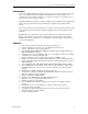
Connect Tech Blue Heat/Net Sync User Manual In the above example, a rapidly flashing CPU LED during the boot up process signifies the Blue Heat/Net Sync has experienced an error. Port LEDs 1 through 4 signify which error has occurred. In this case, LED 2 and 3 are on, so the error code is 6. The chart below defines the error details for each error code. Table 4: LED Error Codes for Blue Heat/Net Sync Error Code and Event 1. Loader code in flash is erased.
Connect Tech Blue Heat/Net Sync User Manual image (uClinux) to run. This will occur when any of the enabled boot sources (flash or BOOTP/TFTP or TFTP) fail to obtain a valid compressed operating system image to run. 6. Unexpected return from the uClinux This error occurs if the operating system returns back to the loader. 5. Cannot obtain an operating system operating system. Check network connections, server computer or your unit's settings.
Connect Tech Blue Heat/Net Sync User Manual 15. Mismatched CDS version number uClinux checks the CDS version number against its expected CDS version number. If they are different, uClinux does not continue its operation. If you have updated the uClinux code via SCM and have not updated the loader/SCM code, this error appears on reboot. Update companion loader code and reboot.
Connect Tech Blue Heat/Net Sync User Manual Set the IP Address Using the Web Configuration Manager NOTE: If you use the Windows Configuration Manager and use Auto Discover to locate your Blue Heat/Net Sync on the network, you can right-click and launch the Web Configuration Manager from there. You only need to use the route add command if you choose not to use the Configuration Manager found on the CD that accompanied your Blue Heat/Net Sync unit. From the command prompt of your computer, run: route add A.
Connect Tech Blue Heat/Net Sync User Manual Blue Heat/Net Sync Configuration The Blue Heat/Net Sync comprises several software components, each of which manages various functions of the Blue Heat/Net Sync. The following is a breakdown of these components.
Connect Tech Blue Heat/Net Sync User Manual program on a PC). Configuration Data Space (CDS) This is the area, in non-volatile (flash) memory, which stores the configuration parameters. CDS (Configuration Data Space) Description The Blue Heat/Net Sync has a number of configuration parameters which are stored in a nonvolatile (flash memory) area. (See appendix for list of parameters). The CDS area is stored redundantly in the flash memory along with a CRC-style checksum to ensure data integrity.
Connect Tech Blue Heat/Net Sync User Manual SCM (Serial Configuration Manager) Description The Serial Configuration Manager is one of the applications you can use to access the Configuration Data Space (CDS) settings of the Blue Heat/Net Sync. Since the CDS stores the default serial port settings, it is important that the line mode is configured prior to first use. Accessing the ports will not be possible otherwise.
Connect Tech Blue Heat/Net Sync User Manual save update Save setting changes to non-volatile flash storage Download a new operating system via TFTP and flash, (uClinux) and loader/SCM image. Command Details boot Syntax: boot [mode=] [file=] [delay=] Description: This command establishes the Blue Heat/Net Sync boot-up mode. For a detailed description of the boot-up process of the Blue Heat/Net Sync, see How the Blue Heat/Net Sync Boots Up in the Appendix.
Connect Tech Blue Heat/Net Sync User Manual password= This sets the password phrase, which is used to gain access to the SCM and WCM modes of configuring the Blue Heat/Net. The default is “password”. prompt= This setting controls whether a password prompt (and other password entry status information) is presented to the terminal. This prompting is helpful for new users of the product but may present a problem when other devices are connected to the serial port.
Connect Tech Blue Heat/Net Sync User Manual [my_ip= | mip=] [server_ip= | sip=] [gateway_ip= | gip=] [subnetmask= | snm=] [broadcast_ip= | bcip=] [dns_ip=] [domain=] [host name=1 host=] [tcp=] [mac=] [dhcp=] Description: Establishes the network settings. Options: network= | net= Sets the “network” portion of the IP address into my_ip, server_ip and gateway_ip. The address entered is masked by the subnet mask setting before being applied.
Connect Tech Blue Heat/Net Sync User Manual mac= This displays the MAC address of the unit. (The default is 00:0C:8B:SS:SS:SS, where SS:SS:SS is the hex value of the serial number of the unit). Note: The MAC address cannot be changed, it can only be displayed. dhcp= This enables or disables DHCP support. yes enables no disables (default) NOTES: All IP addresses are entered in common IP address notation: ddd.ddd.ddd.ddd where ddd is a decimal number from 0 to 255.
Connect Tech Blue Heat/Net Sync User Manual server_ip= | sip= Specify the Server IP address from which the file is to be downloaded. file= Specify the file name to download. If the –jffs option is chosen, then the file= option is mandatory. NOTE: After downloading, the image is checked to ensure the file is correctly formatted. If the file is bad the command exits. The version is checked against your current version. If they match, you will be prompted to choose if you wish to program the flash.
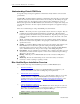
Connect Tech Blue Heat/Net Sync User Manual WCM (Web Configuration Manager) Signing In to the Web Configuration Manager You will need to know the IP address of your Blue Heat/Net Sync unit before you use the Web Configuration Manager. Use the Serial Configuration Manager to assign the Blue Heat/Net Sync a valid IP address, or tell the Blue Heat/Net Sync to use DHCP to automatically obtain an IP address. Please refer to the SCM Command Reference documentation for information on how to do this.
Connect Tech Blue Heat/Net Sync User Manual Figure 14: Blue Heat/Net Sync Settings 32 Revision 0.
Connect Tech Blue Heat/Net Sync User Manual Configure Advanced Serial Settings The Web Configuration Manager also allows you to configure more advanced serial port properties. These advanced properties will allow you to configure the XOn Character, XOff Character, Break Character, Escape Character, Error Character and Event Character, and Transmit Load Setting for each serial port.
Connect Tech Blue Heat/Net Sync User Manual • • • • Server IP Address: This option sets the server IP address. This is used as the Server address to use when bootp mode or TFTP mode is enabled. The default Server IP address is 0.0.0.0 Blue Heat/Net Sync IP Address: This option sets the IP address of your Blue Heat/Net. The default IP address for your Blue Heat/Net Sync is 192.168.42.1 Domain Name: This option sets the domain name of your Blue Heat/Net. The default domain name is blueheat.net.
Connect Tech Blue Heat/Net Sync User Manual Figure 15: Configuring Blue Heat/Net Sync Settings Configure Firmware This section enables you to download new firmware to the Blue Heat/Net Sync unit. Select a download source and a specific firmware file path, if applicable, and then submit the download request. This section also provides a link to reboot your Blue Heat/Net. This is standard procedure after installing new firmware.
Connect Tech Blue Heat/Net Sync User Manual NOTE: This function is not currently operational. Figure 17: Restore Default Settings Saving To Flash When you make configuration changes, the changes are stored temporarily in memory. If you reboot your Blue Heat/Net Sync at this point, any configuration changes you made will be lost. To permanently save your changes, you need to save them to flash.
Connect Tech Blue Heat/Net Sync User Manual Figure 18: Saving To Flash If you haven't made any configuration changes, the Save To Flash button will remain grey. Monitoring Your Blue Heat/Net The Blue Heat/Net Sync WCM lets you monitor serial port activity, network traffic and TCP/IP statistics as well as providing hardware and software details for your Blue Heat/Net Sync unit. Monitor Serial Port Traffic This page allows you to monitor your serial port traffic.
Connect Tech Blue Heat/Net Sync User Manual Monitor Network Traffic This page allows you to view all network activity on your Blue Heat/Net. For each active network connection, you can view the local IP address and port, the remote IP address and port, the status of the connection, the protocol being used, as well as the number of queued transmit and receive bytes.
Connect Tech Blue Heat/Net Sync User Manual Use this link to find information such as device serial number, runtime software versions and firmware versions. Figure 22: My Blue Heat/Net Sync Hardware Details Figure 23: My Blue Heat/Net Sync Software Details Revision 0.
Connect Tech Blue Heat/Net Sync User Manual Software Installation for Windows The Blue Heat/Net Sync is designed for easy installation and set up. This section deals with installing and using the Blue Heat/Net Sync software to communicate with your Blue Heat/Net Sync. To do so, you will use the CD included with the Blue Heat/Net Sync to install the Configuration Manager on your computer.
Connect Tech Blue Heat/Net Sync User Manual Figure 25: Blue Heat/Net Sync Software Installation Screen Revision 0.
Connect Tech Blue Heat/Net Sync User Manual The Blue Heat/Net Configuration Manager Setup Wizard will begin. Click Next to start. Next you will have the option to launch the configuration manager after installation. 42 Revision 0.
Connect Tech Blue Heat/Net Sync User Manual The installer will install the Configuration Manager into C:\Program Files\CTI\Blue Heat Net. If you‟d prefer an alternate location, specify in the space provided, or click Browse to locate the new folder. Click Next. You will then be prompted to confirm you wish to install the Configuration Manager. Select Next to begin. When the Installation Complete window appears, the Configuration Manager has been successfully installed.
Connect Tech Blue Heat/Net Sync User Manual Running the Configuration Manager If you chose the option to launch the Blue Heat/Net Sync Configuration Manager after installation, the main Configuration Manager window should now be open on your screen. If you did not, you can launch it from the CTI default folder or whichever folder you chose during the installation. Figure 26: My Blue Heat/Net Sync Places Screen Device Installation Select My Blue Heat/Net Sync Places from the main Configuration window.
Connect Tech Blue Heat/Net Sync User Manual Configure Default Blue Heat/Net Sync You can choose this option when your Blue Heat/Net Sync still has a factory default IP address of 192.168.42.1. It will launch the Web Configuration Manager for this IP address, enabling you to configure your Blue Heat/Net Sync as outlined in the Web Configuration Manager.
Connect Tech Blue Heat/Net Sync User Manual Auto Discover Blue Heat/Net Sync The auto discover will broadcast a message to all the Blue Heat/Net Sync devices on your network. Upon receiving the broadcast packet, the Blue Heat/Net Sync device will respond. Click the Auto Discover button to search for Blue Heat/Net. The searching domain can be changed by checking Use Specific Broadcast IP and entering an IP address domain in the IP address box.
Connect Tech Blue Heat/Net Sync User Manual Firmware Upgrades If you need to re-install your current firmware, it is located in the firmware directory of the CD you received with your Blue Heat/Net Sync. Newer firmware versions are available from Connect Tech‟s website, http://www.connecttech.com/asp/Support/DownloadZone.asp. Choose Blue Heat/Net Sync product. Ensure the following parameters are set: mip, sip, gip and dns_ip using the SCM.
Connect Tech Blue Heat/Net Sync User Manual Software Development Hardware Information The information provided in this section will offer data pertaining to the hardware components present within the Blue Heat/Net Sync unit. Hardware information documentation will encompass hardware resources, base address map, memory map and table, as well as, PLD registers.
Connect Tech Blue Heat/Net Sync User Manual Interrupts INT * /INT1, /INT2 Usage IUSC logically or-ed interrupts. IUSC Interrupts can be muxed to any of the two INTs. One use is to mux all ports configured for Async mode to one IRQ and all ports configured for Sync mode to another interrupt. This should facilitate better software architecture and operation. /INT3 PLD Interrupt. To support miscellaneous PLD section functions. /INT6 Ethernet PHY Interrupt.
Connect Tech Blue Heat/Net Sync User Manual Memory Map of IUSC and PLD Functions ColdFire (5272) Bus: A ColdFire CS# signal is used to select the entire region, setup with the following attributes… 8K (8192) byte region 16 Bit bus Use TA# signal to terminate the bus cycle (this places wait state generation in the hands of the PLD logic). o CSBR.EBI = 00b selects 16/32 SRAM/ROM mode o CSBR.BW = 10b selects 16 bit bus o CSOR.WS = 0x1F selects the use of the TA# signal o CSOR.
Connect Tech Blue Heat/Net Sync User Manual A[5..1] Addresses IUSC registers (see Memory Map Table below). A[0] Not used explicitly, A0 (along with BS0# and BS1#) select byte size portions of IUSC registers. PLD Resource Access: A[12] Must be one (1). A[11..5] Are not used. A[4..2] Are decoded into selections of internal PLD “registers”.
Connect Tech Blue Heat/Net Sync User Manual Address Offset (in hex) Area (item) Accessed Register Accessed Notes Writes go to the Transmitter FIFO Reads come from the Receiver FIFO 022 024 026 028 02A 02C 02E 030 IUSC-0 Sreg IUSC-0 Sreg IUSC-0 Sreg IUSC-0 Sreg IUSC-0 Sreg IUSC-0 Sreg IUSC-0 Sreg IUSC-0 Sreg RMR RCSR RICR RSR RCLR RCCR TCOR TDR(RDR) 032 034 036 038 03A 03C 03E 040 07F 080->09F IUSC-0 Sreg IUSC-0 Sreg IUSC-0 Sreg IUSC-0 Sreg IUSC-0 Sreg IUSC-0 Sreg IUSC-0 Sreg --IUSC Data FIFO‟s (32
Connect Tech Blue Heat/Net Sync User Manual Address Offset (in hex) 1A0 1A9 1AA 1AC 1AE 1B0 1B9 1BA 1BC 1BE 1C0 1FF 200 202 3FF 400 5FF 600 602-7FF 800 9FF A00 A02 BFF C00 DFF E00 E02 FFF Area (item) Accessed Register Accessed --IUSC-0 Dreg IUSC-0 Dreg IUSC-0 Dreg --IUSC-0 Dreg IUSC-0 Dreg IUSC-0 Dreg --IUSC-0 IUSC-0 --RBCR RARL RARU --NRBCR NRARL NRARU --- Reserved, do not access As Above Same registers as addresses 000 1FF Interrupt Acknowledge (read only) Aliases of 600 As Above --- Same regis
Connect Tech Blue Heat/Net Sync User Manual PLD Registers: Offset Reg Name R/W Valid Bit Bit Descriptions 1000 RTCU Real Time Clock Upper R/W D15..0 Control Bits: Read/Write only as a 16 Bit word. 15 14 13 12 11 10 Msk1 MP MPP MPO IntEN SE Msk1: MP: MPP: MPO: IntEN: SE: EXT: ME: 1002 1004 RTCL Real Time Clock Lower LEDC LED Control Register R/W R/W D15..0 D15..0 0000 9 EXT 8 ME 7 Msk0 6 X 5 X 4 H4 3 H3 2 H2 1 H1 0 H0 On writes, set this bit to mask bits 14..8.
Connect Tech Blue Heat/Net Sync User Manual 1008 100C 1010 1014 LIFC1,2,3,4 Line Interface Control 1008= Port 1 100C = Port 2 1010 = Port 3 1014 = Port 4 R/W D15..0 Control Bits: Read/Write only as a 16 Bit word. 15 14 13 12 11 X DCDC DCDS ES FSM 10 CTSC 9 CTSM1 8 CTSM0 7 RTS 6 DC 5 42W 4 DM 3 SPT 2 SP2 1 SP1 0 SP0 Important Note: These control bits are transferred to ALL the Line Interface PLD‟s by a serial interface.
Connect Tech Blue Heat/Net Sync User Manual 1018 PLD_CNTRL Control Bits R/W D15..0 Control Bits: Read/Write only as a 16 Bit word. 15 14 13 12 11 IM[3] IM[2] IM[1] IM[0] TRG[3] 0000 10 TRG[2] 9 TRG[1] 8 TRG[0] 7 X 6 X 5 IABT 4 SMIE 3 SR[3] 2 SR[2] 1 SR[1] 0 SR[0] IUSC Software Reset: SR[0]=Port1… SR[3]=Port4. Reset is asserted while bit is set to 1. Also, the “Line Interface Control”bits for the given Port, are set back to their power-up state.
Connect Tech Blue Heat/Net Sync User Manual System Block Diagrams Revision 0.
Connect Tech Blue Heat/Net Sync User Manual 58 Revision 0.
Connect Tech Blue Heat/Net Sync User Manual Port Settings, Clock Setup and General Settings Required [conditions] Optional [conditions] (blank) means setting parameter is not required for the mode. TBD means To be Determined at a later date. Serial Mode (smode) BHN_PortSettings smode misc_receiver misc_transmitter r/txclk.ref_freq r/txclk.bps_error r/txclk.bps r/txclk.bps_frac r/txclk.async_div r/txclk.dpll_div r/txclk.ctr_div r/txclk.enc_dec r/txclk.clk_tree.A r/txclk.clk_tree.B r/txclk.clk_tree.
Connect Tech Blue Heat/Net Sync User Manual Serial Mode (smode) BHN_PortSettings sync_addr.rx0 sync_addr.rx1 sync_addr.rx_len sync_addr.strip_sync dbits.t/rx tx_frac_stop parity.t/rx crc.tx_type crc.tx_start crc.tx_mode crc.rx_type crc.
Connect Tech Blue Heat/Net Sync User Manual IUSC Clocking Logic: The following diagram was scanned from the IUSC manual page 4-3 and corrections have been made. Do not use the diagram from the IUSC manual, use the corrected version we have provided below. Revision 0.
Connect Tech Blue Heat/Net Sync User Manual Appendix Blue Heat/Net Sync Specifications Operating Environment 4 port model: 0ºC to 60ºC (32ºF to 158ºF) Communications Baud Rates: Synchronous: Asynchronous: Up to 9.216 Mbps with internal reference clock, up to 10 Mbps with external reference clock. 230.4 Kbps Custom baud rates are also available. Please contact our sales@connecttech.com department for information. ESD Protection 15kV Power Rev A models: 5V (2.
Connect Tech Blue Heat/Net Sync User Manual Protocol Descriptions The Blue Heat/Net Sync supports a variety of protocols. The following is a brief explanation of each and how they are implemented. ARP Address Resolution Protocol, a method used to find a unit‟s Ethernet MAC address from its Internet address. BOOTP Bootstrap Protocol, a protocol that allows a unit to boot from the network instead of using information stored on the Blue Heat/Net Sync (typically in Flash memory).
Connect Tech Blue Heat/Net Sync User Manual Pinouts DB-25 Female Pinouts DB25F Pin # 14 2 16 3 23 20 19 4 13 5 21 6 10 8 11 24 9 17 15 12 22 18 7, 1 [1] [2] [3] [4] [5] [6] [7] Signal Name V.28 in brackets TX+ TX- (TX) RX+ RX- (RX) DTR+ DTR- (DTR) RTS+ RTS- (RTS) CTS+ CTS- (CTS) DSR+ DSR- (DSR) [5] DCD/RX_SYNC_IN+ [5] DCD/RX_SYNC_IN(DCD) [2] TXC+ [2] TXC(TXC) [2] RXC+ [2] RXC(RXC) (TXC) RX_SYNC_OUTRI (RI) TX_TRIGGER [6] SR Line Mode V.35 EIA-530 RS232 (V.28) EIA-530A X.21 (V.11) V.35 [4] V.
Connect Tech Blue Heat/Net Sync User Manual DB-9 Female Pinouts DB9F Pin 1 Signal Name [1] Functional Notes RTC_Clear [3], [6] 2 RTC_Seconds 3 4 5 6 7 8 9 GND EXT_REF_CLK GND TX_TRIGGER_P1 TX_TRIGGER_P2 TX_TRIGGER_P3 TX_TRIGGER_P4 Clears and holds the seconds count of the Real Time Clock at 00. Provides the external time base for the Real Time Clock.
Connect Tech Blue Heat/Net Sync User Manual Multi-drop Communications Using V.11 / RS422/RS485 Line Modes When wiring multi-drop RS-485 networks, it is necessary to wire the devices in a “Daisy Chain”, they must not be wired with a “Star” topology, see diagram. Rack Mount Option: Blue Heat/Net Sync can be rack mounted using the option rack mount kit part number MSG029. 66 Revision 0.
Connect Tech Blue Heat/Net Sync User Manual Default Settings Network Settings Blue Heat/Net Sync IP address Server IP address Gateway IP address Subnet Mask Broadcast IP address Domain Name Server IP address: Domain Name Host Name TCP Port DNS IP 192.168.42.1 0.0.0.0 (used for firmware downloads) 0.0.0.0 255.255.255.0 255.255.255.255 (used by the bootp process) 0.0.0.0 (used for firmware downloads) blueheat.net BHNssssssss (where ssssssss is the BHN serial number) 49152 (0xC000) 0.0.0.
Connect Tech Blue Heat/Net Sync User Manual Common Configuration Setups Static IP Setup In some networking environments it is best to have the IP address set to a fixed value. The advantage is that since it is fixed, connecting to it can be a lot simpler. Static IP is often the best choice if you are trying to connect via WAN or through a Firewall. It can be difficult to resolve the Blue Heat/Net Sync‟s IP address if you use DHCP in this instance. The default configuration is a static IP of 192.168.42.1.
Connect Tech Blue Heat/Net Sync User Manual DHCP Setup In many modern networks IP numbers are not static but are automatically assigned by a DHCP server and can change over time or on each power up. DHCP must be enabled on the Blue Heat/Net Sync because it is shipped to use a default static IP (192.168.42.1) Using SCM Log onto the Blue Heat/Net Sync. The SCM does not require a login. The default password for the SCM is password. Enter net dhcp=yes. This will turn on DHCP on the unit. Enter net dns_ip=3.
Connect Tech Blue Heat/Net Sync User Manual Bootup Sequence Start Boot from Flash Enabled? Decompress uClinux from Flash to SDRAM Y Decompress OK N Y N Bootp Enabled? Obtain boot information from Bootp Server Y Server Responds N N Update CDS (RAM copy) Information (filename & IP address) TFTP Enabled? Y Attempt TFTP Download Y Y Success Decompress Downloaded uClinux into SDRAM N N N Decompress OK Y All Boot Modes Disabled N Display Error on LEDs Run uClinux Y Y Boot Port Persona
Connect Tech Blue Heat/Net Sync User Manual Flowchart of Special Operations Mode using the reset button Power Up Increment Selection Reset Button Held Pressed Yes Show Selection State On Port LEDs No Reset Button Held Wait for Button Release Continue Booting Figure 31: Bootup Sequence via Reset Button Asynchronous Communications Tutorial The Blue Heat/Net Sync features four synchronous/asynchronous serial communication ports.
Connect Tech Blue Heat/Net Sync User Manual Figure 32: Typical Asynchronous Date Frame Serial Line Interface Tutorial RS-232 Line Interface: RS-232 is the simplest, least expensive line interface standard, the Sipex tranceivers used on the Blue Heat/Net Sync refer to RS232 as V.28 mode. It is also referred to as EIA232 and TIA/EIA232. The RS-232 specification signals levels of +3V to +15V for a logic 0 or Space, and -3V to 15V for a logic 1 or Mark.
Connect Tech Blue Heat/Net Sync User Manual mode RS-485 is fully compatible with RS-422; which is considered a subset of RS-485. The use of differential transmitters and receivers ensures RS-485 communications are reliable and robust. This means two wires are used to transmit or receive a signal. One wire carries the true or non-inverted signal; the other wire carries the inverted signal. The non-inverted signal is labelled with a (+) and the inverted is labelled with a (-).
Connect Tech Blue Heat/Net Sync User Manual Multi-drop 4-Wire, Full Duplex Communications: In a multi-drop 4-wire differntial network, two to 32 devices are connected together. Note that each RS-485 receiver counts as a device or “load”. In this multi-drop mode of communication, a master slave protocol must be enforced, that is, all communication is initiated by the master, in this case a Blue Heat/Net Sync.
Connect Tech Blue Heat/Net Sync User Manual Bus Contention on Differential Multi-drop Networks: Bus contention occurs when two or more devices enabled on a bus attempt to run the bus to opposite logic values. From the diagram above, we can see that there are multiple differential transmitters (TXD) on the bus. To avoid the bus contention problem, the differential transmitter features a tri-state, or high impedance mode controlled by an input pin (enable).
Connect Tech Blue Heat/Net Sync User Manual Termination Resistors in Differential Networks Termination Resistors in Differential Networks: Differential networks often benefit from the installation of termination resistors. Termination is rarely required for lower baud rates, for example 9600 baud or less.