
Computer Hardware User Manual


BlueStorm Installation Guide, Connect Tech Inc.
Revision 0.08 11
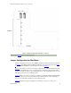
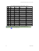
Figure 6: BlueStorm/SP RJ-11 diagram, 8 port model
Note: Refer to Table 8 for port 7 and port 8 pinouts.
Jumper Configuration for BlueStorm
Jumper configurations will vary by model. BlueStorm/LP cards feature the jumper layout listed
in Figure 7, while BlueStorm/SP and BlueStorm/SP Opto cards use the jumper layout in Figure
8. Lastly, BlueStorm/SP RJ-11 uses the jumper layout used in Figure 9.
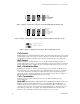
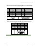
Figure 7 demonstrates a common set of jumper configurations for a BlueStorm/LP RS-422/485
card. BlueStorm/LP RS-232 ports do not require jumper configuration. The four RS-422/485
ports are set as follows: Port 1 is set for half duplex, Port 2 is set for half duplex, Port 3 is set for
full duplex, and Port 4 is set for multi-drop slave.
Figure 8 indicates a common set of jumper configurations for BlueStorm/SP and BlueStorm/SP
Opto. The four ports are set as follows: Port 1 is set for RS-232, Port 2 is set for half duplex,
Port 3 is set for full duplex, and Port 4 is set for multi-drop slave.
Figure 9 illustrates the jumper configurations for selecting +5V power or +12V power.
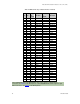
6 x RJ-11
Pin 1 Pin 1