BlueStorm Universal PCI User Manual Contact Information: Connect Tech Inc. 42 Arrow Road Guelph, Ontario, Canada N1K 1S6 Tel: 519-836-1291 (International) 800-426-8979 (Canada & USA) Fax: 519-836-4878 Email: sales@connecttech.com support@connecttech.com URL: www.connecttech.com CTIM-00015 Revision 0.
BlueStorm Installation Guide, Connect Tech Inc. Limited Lifetime Warranty Connect Tech Inc. provides a lifetime warranty for all* Connect Tech Inc. products. Should this product, in Connect Tech Inc.'s opinion, fail to be in good working order during the warranty period, Connect Tech Inc. will, at its option, repair or replace this product at no charge, provided that the product has not been subjected to abuse, misuse, accident, disaster or non Connect Tech Inc. authorized modification or repair.
BlueStorm Installation Guide, Connect Tech Inc. Table of Contents Limited Lifetime Warranty ..............................................................................................................................2 Copyright Notice..............................................................................................................................................2 Trademark Acknowledgment...........................................................................................................
BlueStorm Installation Guide, Connect Tech Inc. List of Tables Table 1: DB-25 Male Pinouts for BlueStorm/LP (2 Port Connector)........................................................... 13 Table 2: HDB-44 Pinouts for BlueStorm/LP (4 Port Connector)................................................................. 14 Table 3: VHDCI-68 Female Pinouts for BlueStorm/LP (8 Port Connector) ................................................ 16 Table 4: HDB-78 Pinouts for BlueStorm/SP (8 Port Connector) .............
BlueStorm Installation Guide, Connect Tech Inc. Customer Support Overview If you experience difficulties after reading the manual and/or using the product, contact the Connect Tech Inc. reseller from which you purchased the product. In most cases the reseller can help you with product installation and difficulties. In the event that the reseller is unable to resolve your problem, our highly qualified support staff can assist you.
BlueStorm Installation Guide, Connect Tech Inc. Introduction Connect Tech Inc. presents BlueStorm/LP/SP/SP Opto and SP RJ-11. These high-speed multiport communication adapters are designed for Low Profile (LP) and Standard Profile (SP) PCI compatible computers. BlueStorm cards provide you with up to eight high performance serial ports and baud rates up to 1.8432 Mbps that are compatible with any standard serial communications application. BlueStorm cards are fully PCI compliant.
BlueStorm Installation Guide, Connect Tech Inc. BlueStorm Installation Overview There are three stages to installing your BlueStorm card: 1. Hardware Configuration Interrupts and Memory selection will be set by the host computer’s BIOS and operating system. This section outlines jumper settings and configuration. 2. Hardware Installation Installation involves the physical installation of the BlueStorm into your computer.
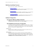
BlueStorm Installation Guide, Connect Tech Inc. Multi-drop Slave Mode In this mode the TxD+/- line driver is enabled only when data is transmitted and RxD+/- is enabled at all times. This mode is typically used in multi-drop 4-wire connections. This mode requires software setup in Control Panel – System Properties – Hardware - Device Manager – Ports – CTI PCI UART. Click on Advanced under Port Settings.
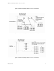
BlueStorm Installation Guide, Connect Tech Inc. Figure 1: BlueStorm/LP Jumper Block Locations (2 Port Models) • • • • • • • • • • • • Jx1 Jx2 Jx3 Jx4 Jx5 Jx6 Figure 2: BlueStorm/LP Jumper Block Locations (4 Port Models) Figure 3: BlueStorm/LP Jumper Block Locations (8 Port Models) Revision 0.
BlueStorm Installation Guide, Connect Tech Inc. Female HDB-78 •••••• •••••• •••••• •••••• •••••• •••••• •••••• •••••• •••••• •••••• •••••• •••••• Note: Jumper blocks are not installed for ports only capable of communicating in RS-232.
BlueStorm Installation Guide, Connect Tech Inc. Pin 1 Pin 1 6 x RJ-11 )Figure 6: BlueStorm/SP RJ-11 (8 Port Model) Note: Refer to Table 8 for port 7 and port 8 pinouts. Jumper Configuration for BlueStorm Jumper configuration options will vary by model. BlueStorm/LP RS-422/485 cards feature the jumper layout listed in Figure 7, while BlueStorm/SP and BlueStorm/SP Opto cards use the jumper layout in Figure 8. Lastly, BlueStorm/SP RJ-11 uses the jumper layout used in Figure 9.
BlueStorm Installation Guide, Connect Tech Inc. Figure 9 illustrates the jumper configurations for selecting +5V power or +12V power.
BlueStorm Installation Guide, Connect Tech Inc. the operating system is booted by the current driver/software RS-485 mode. The jumper is used to ensure that a port will power-on tri-stated. For example, the RS-485 mode selection in the Windows control panel will override this jumper setting once a port is opened. The BlueStorm/LP RS-422/485 uses JC to configure Auto-485 mode, while the BlueStorm/SP Opto uses J1. Note that on BlueStorm/LP RS-422/485 models the Auto 485 is a single jumper.
BlueStorm Installation Guide, Connect Tech Inc. 19 20 21 22 23 24 25 2 1 1 2 2 DTR DTR NC RI RI NC DCD output output no connect input input no connect input RXDRXDNC CTS+ CTS+ NC RXD+ input input no connect input input no connect input Cable CBG002 sends the signals to two DB-9 male connectors. See Table 6 for pinout details. NOTE: This is not the pinout of DB-25 cable CBG007. Table 2: HDB-44 Pinouts for BlueStorm/LP (4 Port Connector) Pin No.
BlueStorm Installation Guide, Connect Tech Inc. 38 39 40 41 42 43 44 3 3 3 4 4 4 NC DSR DTR RI DSR DTR RI no connect input output input input output input NC CTSRXDCTS+ CTSRXDCTS+ no connect input input input input input input Cable CBG003 sends the signals to four DB-9 male connectors. Cable CBG007 sends the signals to four DB-25 connectors. See Table 6 for pinout details. Revision 0.
BlueStorm Installation Guide, Connect Tech Inc. Table 3: VHDCI-68 Female Pinouts for BlueStorm/LP (8 Port Connector) Pin No. 1 2 3 4 5 6 7 8 9 10 11 12 13 14 15 16 17 18 19 20 21 22 23 24 25 26 27 28 29 30 31 32 33 34 35 36 37 38 39 40 41 42 43 44 45 46 Port No.
BlueStorm Installation Guide, Connect Tech Inc. Table 3: VHDCI-68 Female Pinouts for BlueStorm/LP (Continued) Pin No. 47 48 49 50 51 52 53 54 55 56 57 58 59 60 61 62 63 64 65 66 67 68 Port No. 6 6 6 6 5, 6 7, 8 7 7 7 7 7 7 7 7 8 8 8 8 8 8 8 8 RS-232 Signal RTS DSR RXD CTS SG SG TXD RI DCD DTR RTS DSR RXD CTS TXD RI DCD DTR RTS DSR RXD CTS Signal Direction output input input input signal gnd. signal gnd.
BlueStorm Installation Guide, Connect Tech Inc. Table 4: HDB-78 Pinouts for BlueStorm/SP (8 Port Connector) Pin Port RSNo. No.
BlueStorm Installation Guide, Connect Tech Inc. Table 4: HDB-78 Pinouts for BlueStorm/SP (Continued) Pin Port RSNo. No.
BlueStorm Installation Guide, Connect Tech Inc. Table 5: RJ-45 Pinouts for BlueStorm/SP Opto (4 Port Connector) Pin No. 1 2 3 4 5 6 7 8 9 10 RS-232 Signal N/C N/C RTS SG TxD RxD Gnd CTS N/C N/C RS-422/485 Signal RTS (-) RxD (+) RTS (+) SR TxD (+) RxD (-) Gnd. CTS (+) TxD (-) CTS (-) Direction no connect input output signal gnd output input ground input no connect no connect Direction output input output signal ref.
BlueStorm Installation Guide, Connect Tech Inc. Table 6: Pinouts and Control Signals for DB-9 and DB-25 Male Connectors (BlueStorm/LP and BlueStorm/SP Only) Pin # DB-9 DB-25 1 8 2 3 3 2 4 20 5 7 6 6 7 4 8 5 9 22 Signal DCD RxD TxD DTR SG DSR RTS CTS RI RS-232 Signal Direction input input output output signal gnd. input output input input Signal RxD + TxD + TxD – RxD – SR CTS – RTS – RTS + CTS + DB-9 male RS-422/485 Signal Direction input output output input signal ref.
BlueStorm Installation Guide, Connect Tech Inc. Table 8: RJ-11 Pinouts for BlueStorm/SP RJ-11 (Ports 7 and 8 Only) Pin No. 1 2 3 4 5 6 7 8 9 10 RS-232 DCD DSR RxD RTS TxD CTS DTR RI SG N/C Direction input input input output output input output input signal gnd. no connect 1 2 3 4 5 6 7 8 9 10 P7/P8 Please note that ports 7 and 8 are not accessible through the factory installed bracket.
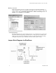
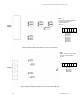
BlueStorm Installation Guide, Connect Tech Inc. External I/O Box (part number: IOBG08BLV1) Male DB-9 connectors Mounting bracket VHDCI-68 connector Figure 10: BlueStorm External I/O Box Diagram Note: View VHDCI-68 connector pinouts in Table 3. I/O box IOBG08BLV1 will send the signals to eight DB-9 male connectors. See Table 6 for the DB-9 pinouts. Revision 0.
BlueStorm Installation Guide, Connect Tech Inc.
BlueStorm Installation Guide, Connect Tech Inc. Hardware Installation Turn the power off to your computer and open it to expose the expansion slots (consult your system’s documentation for more information about this procedure). Choose an available PCI expansion slot, remove the expansion slot cover and insert the BlueStorm adapter, pushing down gently until the board seats fully in the slot. Secure the BlueStorm card to the computer chassis.
BlueStorm Installation Guide, Connect Tech Inc.
BlueStorm Installation Guide, Connect Tech Inc. Certification Connect Tech Inc. declares that the product(s) covered by the contents of this manual have been tested and found compliant with the below listed standards as required by the Electromagnetic Compatibility (EMC) Directive for General Immunity Compliance, EN 50 0082.