
Technical data

Technology functions
CPU 317T: Technology Functions
A5E00251798-03
6-145
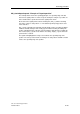
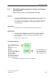
MC_CamInSuperImposed - Example of "Superimposition"
The example below shows the operating principle of a superimposing cam disk,
based on its signal profile. In order to keep the example as simple as possible, we
have excluded base synchronism from the signal profile shown.
At the start of the signal profile, both the leading axis (Axis_1) and the following
axis (Axis_2) have a start position > 0. The default superimposing position of the
slave starts at 0.
Exe_1 starts superimposing camming. Synchronization starts according to Mode =
0 with the default settings in S7T Config (synchronization starting at leading axis
position 100 with dynamic setpoints.) Synchronization starts when the leading axis
has reached (Axis_1) position 100. After a short delay, InSync_1 reports that cam
synchronism is reached.
The signal flow highlighted in orange color indicates the superimposing slave
position. The slave position follows according to its start position and with constant
offset to the superimposing slave position.