
Technical data

Basic functions
4.2 Homing
Connection of the SINAMICS S120 to the Technology CPU
Product Information, 09/2011, A5E00480378-04
109
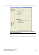
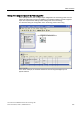
3. The logical hardware address of the homing output cam (BERO) must be specified.
As described above, the first integrated digital input should be used in this example.
This is configured with hardware address byte 66 and bit 0.
"Start of homing procedure" specifies the approach direction (counting direction)
of the Bero
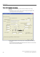
4. Enter appropriate values in the "Approach velocity", "Entry velocity", and
"Reduced velocity" input boxes.
This completes the configuring of the technological part of the homing function in
S7T Config.
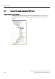
Creating the S7 user program
Use the Technology Object Manager (TOM) to create a technology data block (TO-DB),
which is assigned to the homing output cam technology object. The technology data block
(TO-DB) allows the functions on the associated technology object to be executed using the
provided FBs. For the homing, use the FB403 MC_Home function block in your S7 program.
4.2.3 Example: Active homing using only an external zero mark
Introduction
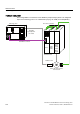
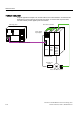
An external zero mark (Bero) should be used for homing the axis. This requires that one of
the fast integrated digital inputs of the SINAMICS S120 is used. Special configuration steps
must be carried out for this, and these are described below.
Operational sequence
The position is accepted when one of the defined BERO edges is passed.