
Technical data

Commissioning
3.2 Connecting hardware components
Connection of the SINAMICS S120 to the Technology CPU
Product Information, 09/2011, A5E00480378-04
21
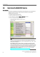
3.2.3 Additional hardware wiring for Smart Line Modules without DRIVE-CLiQ
For Smart Line Modules without a DRIVE-CLiQ interface, the signals of these modules must
be connected through hardware wiring with the CU320 control unit.
The following signals must be wired between the Smart Line Module (SLM) and the
CU320 control unit.
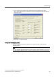
Signal SLM TB30 Comment
SLM Ready DO: X21.1 ⇨ DI: X481.1 SLM operational
Overtemperature
Prewarning
DO: X21.2 ⇨ DI: X481.3 Overtemperature
prewarning
Reset DI: X22.3 ⇦ DO: X481.5 Reset faults
The wiring using the TB30 Terminal Board on the SINAMICS S120 was realized in the table.
As an alternative to the wiring using the digital inputs of the TB30 Terminal Board, the wiring
can also be made directly at the digital inputs of the CU320 control unit.
CAUTION
Damage to the infeed.
If the operational signal of the Smart Line Module (SLM) is not wired to the control unit and
evaluated there, this can cause damage to the infeed.
Detailed information on the wiring is available in the documentation on the
SINAMICS S120 drive system available on the Internet
(http://apps01.industry.siemens.com/
c
ontent/00000100/Content/syn_s120.aspx?rc=1).