
Technical data

Commissioning
3.4 Configuring the drive components
Connection of the SINAMICS S120 to the Technology CPU
70 Product Information, 09/2011, A5E00480378-04
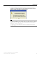
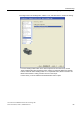
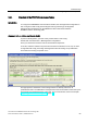
Alignment with a Smart Line Module (SLM)
To perform the alignment, open the message frame configuration in S7T Config
(same as for the ALM), and check and correct the order of the individual components there.
To do this, select the relevant component, and use the arrow buttons to move it up or down.
The objects must be kept in the following order:
1. Drives
2. Option modules
3. Control unit
The alignment procedure is the same as with an Active Line Module (ALM)
This concludes the configuration. You can check the topology of your
SINAMICS configuration. For more information, refer to the section
"Diagnosing the SINAMICS configu
r
ation (Page 75)".
See also
Extending a PROFIdrive message frame (Page 130)
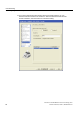
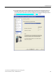
3.4.5 Loading the configuration into the drive components
Procedure
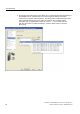
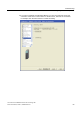
Once the configuration in S7T Config is complete, save and compile the settings and
interconnections you have made. Now switch to online mode and load the configuration into
the SINAMICS S120.
To do so, select SINAMICS_S120. In the context menu,
select the Target Device > Download command.
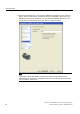
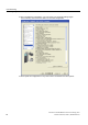
Note
If an error occurs during the save and compile operation, you should check the
HW Config settings for constant bus cycle time and the DP cycle on the
PROFIBUS DP (Drive).