Xtreme/104 Plus, PCI-104 and PCI/104 Express Family User Manual Connect Tech Inc. 42 Arrow Road Guelph, Ontario N1K 1S6 Tel: Toll: Fax: Email: Web: 519-836-1291 800-426-8979 (North America only) 519-836-4878 sales@connecttech.com support@connecttech.com www.connecttech.com CTIM-00029 Revision 0.
Connect Tech Xtreme/104-Plus, PCI-104 and PCI/104 Express Family User Manual 1 Limited Lifetime Warranty Connect Tech Inc. provides a lifetime warranty for all of our products. Should this product, in Connect Tech Inc.’s opinion, fail to be in good working order during the warranty period, Connect Tech Inc. will, at our option, repair or replace this product at no charge, provided that the product has not been subjected to abuse, misuse, accident, disaster or non Connect Tech Inc.
Connect Tech Xtreme/104 Plus, PCI-104 and PCI/104 Express Family User Manual 4 Table of Contents 1 2 3 4 5 6 7 8 9 10 11 12 13 14 15 16 17 18 Limited Lifetime Warranty ............................................................................................................................... 2 Copyright Notice ............................................................................................................................................... 2 Trademark Acknowledgment ...................
Connect Tech Xtreme/104-Plus, PCI-104 and PCI/104 Express Family User Manual Line Interface Mode Jumpers for XIG 12 Port Opto ................................................................ 28 18.4.1 Line Interface Mode Jumpers for XIG 12 Port Opto (table view) ....................................28 18.5 Bias and Termination Resistors XIG 12 Port Opto .................................................................. 29 18.6 Power-on Tri-state for XIG 12 Port Opto .........................................
Connect Tech Xtreme/104 Plus, PCI-104 and PCI/104 Express Family User Manual Figure 20: RS-422/485 Wiring Diagram (4 Wire) ........................................................................................41 Figure 21: RS-422/485 Wiring Diagram (4 Wire Multidrop) .......................................................................41 Figure 22: RS-422/485 Wiring Diagram (2 Wire) ........................................................................................41 4.
Connect Tech Xtreme/104-Plus, PCI-104 and PCI/104 Express Family User Manual 5 Revision Changes Rev 0.12 Date Dec 6, 2012 Change Updated information in regards to the XIG 12 Port Opto. - Added new picture for Rev C model, including power jumper changes. - Restated power consumption for the XIG 12 Port Opto, added typical and max for RS485. - Low Power shutdown feature has been removed, Slow Slew rate feature added. See section Low Power Shutdown for more detail.
Connect Tech Xtreme/104 Plus, PCI-104 and PCI/104 Express Family User Manual Technical Support representatives are ready to answer your call Monday through Friday, from 8:30 a.m. to 5:00 p.m. Eastern Standard Time. Our numbers for calls are: Telephone: Telephone: Facsimile: 800-426-8979 (North America only) 519-836-1291 (Live assistance available 8:30 a.m. to 5:00 p.m.
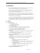
Connect Tech Xtreme/104-Plus, PCI-104 and PCI/104 Express Family User Manual 9 Introduction Connect Tech's Xtreme/104-Plus, 104-PCI and 104/Express family combines the best of the Universal PCI bus with the rugged and compact form factor of PC/104. The various models are PCI 2.0, PC/104-Plus 2.0 or PCIe/104 compliant. The modular Xtreme/104-Plus and Xtreme/104-Plus Opto cards include a PC/104 pass-through connector option for compatibility with legacy PC/104 cards.
Connect Tech Xtreme/104 Plus, PCI-104 and PCI/104 Express Family User Manual 9.1.2 Xtreme/104-Plus Opto Universal PC/104-Plus adapter PCI 2.0 and PC/104-Plus compliant 2 or 4 ports jumper selectable for RS-232/422/485 Supports full duplex, half duplex and multi-drop communication modes in RS-422/485 Maximum data rates of 921.6 Kbps (RS-232) and 1.
Connect Tech Xtreme/104-Plus, PCI-104 and PCI/104 Express Family User Manual 9.1.4 Xtreme/PCI-104 12 Port Opto (XIG) 10 PCI-104 Version 1.0 compliant Highest port density isolated serial board on the market! 12 ports with jumper selectable for RS-232/422/485 Supports full duplex, half duplex and multi-drop communication modes in RS-422/485 Maximum data rates of 921.6 Kbps (RS-232) and 4.166Mbps (RS-422/485) with 8x baud clock.
Connect Tech Xtreme/104 Plus, PCI-104 and PCI/104 Express Family User Manual 10 Xtreme/104-Plus Diagrams Figure 1: Xtreme/104-Plus RS-232/422/485 4 and 8 port models hardware components Revision 0.
Connect Tech Xtreme/104-Plus, PCI-104 and PCI/104 Express Family User Manual Figure 2: Xtreme/104-Plus RS-423 Model Hardware Components 12 Revision 0.
Connect Tech Xtreme/104 Plus, PCI-104 and PCI/104 Express Family User Manual Figure 3: Xtreme/104-Plus RS-232/422/485/TTL Models Revision 0.
Connect Tech Xtreme/104-Plus, PCI-104 and PCI/104 Express Family User Manual Note: Configuration information for the RS-232/422/485/TTL model, including jumper settings and pinouts, is located in Electrical Interfaces (RS-232/422/485/TTL models). Figure 4: Xtreme/104-Plus Opto RS-232/422/485 Hardware Components (4 Port Model) 14 Revision 0.
Connect Tech Xtreme/104 Plus, PCI-104 and PCI/104 Express Family User Manual Figure 5: Xtreme/104-Plus 16 Port RS-232/422/485 Hardware Components Revision 0.
Connect Tech Xtreme/104-Plus, PCI-104 and PCI/104 Express Family User Manual 11 Xtreme/104 Express Diagrams Port I/O connectors 2x5 R/A headers Line Interface selection jumpers J19 J17 J14 J15 J16 J13 J9 J4 J10 Ports 1-4 J11 J12 RS485 control jumpers P5 P4 J3 J5 P6 P3 J2 J6 P7 P2 J1 J7 P8 Ports 5-8 J8 P1 P10 PCI/104 Express Connector Figure 6: Xtreme/104-Express Opto 4 and 8 port Hardware Components 16 Revision 0.
Connect Tech Xtreme/104 Plus, PCI-104 and PCI/104 Express Family User Manual 12 Xtreme/PCI104 12 Port Opto Diagrams Port 12 Port 1 J12.1 J12.2 J1.2 J1.1 J11.1 J12.2 J2.2 J10.1 J10.2 J3.2 J2.1 J3.1 J9.1 J4.1 J9.2 J4.2 J8.2 J5.2 J8.1 J5.1 Port 7 Port 6 J7.1 J6.2 G-485 P-9-12 P-5-8 P-1-4 J7.2 F E D C BA AB J6.
Connect Tech Xtreme/104-Plus, PCI-104 and PCI/104 Express Family User Manual 13 Xtreme/104 Installation Overview Before you begin, take a moment to ensure your package includes the components shipped with your product. These components should include: One Xtreme/104 adapter One CD containing software and documentation DB-9 male fan-out cable or DB9 male cables (optional) If any of these components are missing, contact Connect Tech (see more Contact Details) or your reseller.
Connect Tech Xtreme/104 Plus, PCI-104 and PCI/104 Express Family User Manual 15 Hardware Configuration 15.1 Safety note To ensure the most reliable and safe operation, never install or remove jumpers or adjust the rotary switch while the power is on! 15.2 Interrupts and Memory Address Selection Xtreme/104 boards are PCI and PCI Express cards, so the host computer’s BIOS or Operating System will automatically set interrupts and memory addresses when you reboot after installation. 15.
Connect Tech Xtreme/104-Plus, PCI-104 and PCI/104 Express Family User Manual 15.3.2 Xtreme/104 Plus and /PCI-104 ID Selection Using the Jumper Block If your Xtreme/104-Plus or Xtreme/PCI-104 card is equipped with a jumper block for ID selection, set your board’s location by changing jumper positions. Figure 7 depicts the jumper settings required for each ID. The jumpers remain unpopulated for an ID of zero.
Connect Tech Xtreme/104 Plus, PCI-104 and PCI/104 Express Family User Manual 16 Electrical Interfaces Xtreme/104 Plus and Express (RS-232/422/485 and RS-423 Models) 16.1 RS-232 Electrical Interface This is the default setting for the interface selectable Xtreme/104-Plus and Xtreme/104-Plus Opto. To operate a port in RS-232 mode, no jumpers are set on the corresponding jumper block. 16.
Connect Tech Xtreme/104-Plus, PCI-104 and PCI/104 Express Family User Manual 16.3 Jumper Block Settings The following jumper block diagram depicts typical settings on a four-port selectable Xtreme/104-Plus or Xtreme/104-Plus Opto. Jumper blocks JA, JB, JC and JD control ports 1 through 4, respectively. The Xtreme/104 Express can have 4 or 8 ports which are controlled by J1 though J4, and J1 though J8 respectively.
Connect Tech Xtreme/104 Plus, PCI-104 and PCI/104 Express Family User Manual 16.3.3 Jumper Details RS-485 Selection: Install this jumper to configure a port for RS-422/485 mode. If the jumper is not installed, the port will function in RS-232 mode. TxD Control: Install this jumper to only enable the RS-485 transmitter when sending data. This mode is useful for half-duplex operation when only one device is allowed to send data at a time.
Connect Tech Xtreme/104-Plus, PCI-104 and PCI/104 Express Family User Manual 16.4 Power-on RS485 Tri-state for multidrop networks. Xtreme/104- Opto models offer a power-on tri-state feature to ensure glitch-free power-up on multi-drop networks. When enabled, the Xtreme/104- Opto will hold the RS-485 transmitter in tri-state at power up. This feature is available on ports configured as RS-485 half duplex or RS485 4-wire multi-drop.
Connect Tech Xtreme/104 Plus, PCI-104 and PCI/104 Express Family User Manual 17 Electrical Interfaces (RS-232/422/485/TTL Models) 17.1 RS-232/TTL Electrical Interface The following control signals are available to ports configured for RS-232 and TTL mode: TxD, RxD, RTS, CTS, RI, DTR, DSR, DCD, SG (Signal Ground) and +5V. See Figure 3 for the location of Px1 RS-232/TTL port headers. See Figure 13 for information on configuring ports for RS-232 or TTL mode.
Connect Tech Xtreme/104-Plus, PCI-104 and PCI/104 Express Family User Manual 18 Electrical Interfaces XIG 12 Port Opto 18.1 I/O Port Power for the XIG 12 Port Rev A/B Models Jumpers J2A, J2B and J2C provide the ability to power on or off the I/O section of a port in groups of four. Removing the jumpers will remove power from the DC-DC converter and all components in the isolated section of the product. This mode can be used in cases where power is in short supply and the group of ports is unused.
Connect Tech Xtreme/104 Plus, PCI-104 and PCI/104 Express Family User Manual 18.3 Line Modes XIG 12 Port Opto 18.3.1 Low Power Shutdown This mode has been removed from Rev C models. It was found to not provide a significant power savings due to the low efficiency of DC-DC converters at low loading. The “Slow Slew Rate” feature was added in Rev C models, see below. Rev C models have other design improvements which should provide lower power consumption overall. 18.3.
Connect Tech Xtreme/104-Plus, PCI-104 and PCI/104 Express Family User Manual 18.4 Line Interface Mode Jumpers for XIG 12 Port Opto The following jumper block diagram depicts typical settings on a four-port selectable Xtreme/PCI-104 12 Port Opto. Each port has two banks of jumper blocks, Jx.1y and Jx.2y. Where ‘x’ is the port number and ‘y’ is the jumper number of that power.
Connect Tech Xtreme/104 Plus, PCI-104 and PCI/104 Express Family User Manual 18.5 Bias and Termination Resistors XIG 12 Port Opto The (B&T) Bias and Termination resistors are use in RS485 communications. All other modes these jumpers should be removed. The B&T resistors are selected using jumpers Jx.1E/Jx.1F (4-wire networks) and Jx.2A/Jx.2B (2-wire networks).
Connect Tech Xtreme/104-Plus, PCI-104 and PCI/104 Express Family User Manual ……power considerations continued A typical current draw under RS485 is about 900mA (4.5 Watts) which occurs under the following conditions: All ports RS485 4-wire mode. Bias and Termination (B&T) circuit installed all ports (provides bias and termination on the RX+/- signals). Remote end or device end with 120 ohm termination resistor installed on RX+/-. 5-10 remote devices per port.
Connect Tech Xtreme/104 Plus, PCI-104 and PCI/104 Express Family User Manual 20 Driver Software Configuration 20.
Connect Tech Xtreme/104-Plus, PCI-104 and PCI/104 Express Family User Manual 21 Connectors/Pinouts 21.1 40 Pin Connector Pin Numbering Figure 16: 40 Pin Connector: Pin Numbering 21.2 80 Pin Connector Pin Numbering Figure 17: 80 Pin Connector: Pin Numbering 32 Revision 0.
Connect Tech Xtreme/104 Plus, PCI-104 and PCI/104 Express Family User Manual 21.
Connect Tech Xtreme/104-Plus, PCI-104 and PCI/104 Express Family User Manual 21.4 Xtreme/104 Plus RS-232/422/485 Table 2: I/O Signal Assignments for RS-232/422/485 Models) 34 Header Port No. (4 port models) Header Port No. (8 port models) Pin No.
Connect Tech Xtreme/104 Plus, PCI-104 and PCI/104 Express Family User Manual 21.
Connect Tech Xtreme/104-Plus, PCI-104 and PCI/104 Express Family User Manual 21.6 Xtreme/104 Plus Opto 2 & 4 Port, Xtreme/104-Express Opto 8 Port Table 4: 10 Pin R/A Port Header Pinouts on Opto Models Pin No. 1 2 3 4 5 6 7 8 9 10 RS-232 NC NC RxD RTS TxD CTS NC NC isolated gnd. N/A Direction NC NC input output output input NC NC signal gnd. N/A Direction RxD (+) CTS (-) RxD (-) RTS (+) TxD (+) CTS (+) TxD (-) RTS (-) isolated gnd.
Connect Tech Xtreme/104 Plus, PCI-104 and PCI/104 Express Family User Manual 21.7 XIG 12 Port Opto Table 5: 10 Pin R/A Port Header Pinouts on 12 Port Opto Models Pin No.
Connect Tech Xtreme/104-Plus, PCI-104 and PCI/104 Express Family User Manual 22 Cable Pinouts 22.
Connect Tech Xtreme/104 Plus, PCI-104 and PCI/104 Express Family User Manual 22.3 Xtreme/104 Plus RS232/485/TTL model Table 8: RS-232/TTL Px1 Right Angled Header Pinouts (CAG104 Compatible) (See Figure 3 for port numbering and locations) Pin # 1 2 3 4 5 6 7 8 9 10 RS-232/TTL Signal DCD DSR RxD RTS TxD CTS DTR RI SG +5V Direction Input Input Input Output Output Input Output Input Signal Ground supply to external devices Note: Total current drawn on +5V pins of all ports must not exceed 1A.
Connect Tech Xtreme/104-Plus, PCI-104 and PCI/104 Express Family User Manual 23 Wiring Examples 23.1 RS232 Wiring Example Xtreme/104 RS232 Device TxD RxD GND CTS RTS RxD TxD GND RTS CTS Figure 18: RS-232 Wiring Diagram 23.2 RS423 Wiring Example Xtreme/104 TxDRef GND RxDRxD+ RS232 Device TxDTxD Ref GND RXDRxD+ RxDRxD+ GND TxDRef Figure 19: RS-423 Wiring Diagram 40 Revision 0.
Connect Tech Xtreme/104 Plus, PCI-104 and PCI/104 Express Family User Manual 23.3 RS-422/485 Wiring Examples Note: The RS-422/485 electrical interface consists of a differential signaling scheme. You should always connect the signals with twisted pairs. The Signal Reference (GND) must be connected.
Connect Tech Xtreme/104-Plus, PCI-104 and PCI/104 Express Family User Manual 24 Specifications 24.1 Operating Environment Storage temperature: -40 C to 125 C Operating temperature: 0 C to 70 C (Commercial temperature models) -40 C to 85 C (Industrial temperature models) Humidity: 95% non-condensing 24.2 Power Requirements Xtreme/104-Plus RS-423 models +5 V DC +/-5% @ 100 mA (max.) 2 port models Xtreme/104-Plus RS-232/422/485 models +5 V DC +/-5% @ 385 mA (max.
Connect Tech Xtreme/104 Plus, PCI-104 and PCI/104 Express Family User Manual 24.7 Communications 24.7.1 Baud Rates most models: RS-232/TTL: RS-422/485: RS-423: PC/104 Plus Models: 50 bps – 921.6 Kbps PCI/104 Express models: Any standard baud rate up to 921.6Kbps * PC/104 Plus Models: 50 bps – 1.8432 Mbps PCI/104 Express models: Any standard baud rate up to 7.812Mbps * 50 bps – 115.2 Kbps Baud rates 12 and 16 Port models based on Actel FPGA and Exar UARTs: RS-232: RS-422/485: 50bps – 1.0Mbps * 50bps – 4.
Connect Tech Xtreme/104-Plus, PCI-104 and PCI/104 Express Family User Manual 24.8 Certification The Xtreme/104-Plus and Express product families are to be included into a device ultimately subject to FCC, DOC/IC, and CE certification. The customer is responsible for bringing the completed device into compliance prior to resale. Connect Tech Inc.