
User manual

Connect Tech Xtreme/104 Plus, PCI-104 and PCI/104 Express Family User Manual
Revision 0.11
29
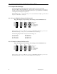
18.5 Bias and Termination Resistors XIG 12 Port Opto
The (B&T) Bias and Termination resistors are use in RS485 communications. All other modes
these jumpers should be removed.
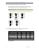
The B&T resistors are selected using jumpers Jx.1E/Jx.1F (4-wire networks) and Jx.2A/Jx.2B
(2-wire networks).
RXD and TXD/RXD Termination/Bias: Install this pair of jumpers to enable a 150 ohm
terminator across the RxD+/- signals for 4-wire modes, and TxD/RxD+/- for 2-wire modes for
the corresponding port. A biasing network is also enabled that drives the receiver to an inactive
or safe mode. The receiver can still receive data from another device and the biasing helps to
prevent the reception of data generated by noise on the transmission line. The two jumpers for
the termination/bias must be installed and removed as a pair.
Bias and Termination Notes:
For 2-wire and 4-wire multidrop wiring networks the B&T resistors must only be
installed when the Xtreme/PCI-104 12 Port Opto is the first or last device in the wiring
network.
4-wire networks must only use the Jx.1E/Jx.1F jumpers.
2-wire networks must only use the Jx.2A/Jx.2B jumpers.
Never have both pairs of B&T resistors installed!
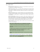
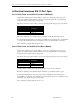
18.6 Power-on Tri-state for XIG 12 Port Opto
The XIG offers a power-on tri-state feature to ensure glitch-free power-up on multi-drop
networks. When enabled, the Xtreme/104- Opto will hold the RS-485 transmitter in tri-state at
power up. This feature is available on ports configured as RS-485 half duplex or RS-485 4-wire
multi-drop.
Note: Enabling this feature on ports configured in RS-232 or RS-422 (RS-485 full duplex)
modes will disrupt the operation of the RTS signal.
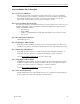
Jumper G-485 in J2 controls the power-on tri-state functionality. Install a jumper on this jumper
to enable the Power on Tri-State function.
18.7 Power considerations for the XIG 12 Port Opto
Under worst case RS485 operations the XIG can draw significant current.
The XIG can draw up to 1400mA from the 5V rail under the most extreme RS485 conditions. Under these
condition the power dissipation is 1400mA*5V = 7 Watts. The conditions for this are as follows:
All ports RS485 4-wire mode.
Bias and Termination (B&T) circuit installed all ports (provides bias and termination on
the RX+/- signals).
Remote end or device end with 120 ohm termination resistor installed.
TX +/- and RTS +/- with external 120 ohm terminator installed all ports.
31 remote devices connected per port.