Instruction Manual TEC-9300 Self-Tune Fuzzy / PID Process Temperature Controller Agency Approvals: RoHS Serving Industry Since 1972 TEMPCO Electric Heater Corporation 607 N. Central Avenue • Wood Dale, IL 60191-1452 USA Tel: 630-350-2252 • Toll Free: 800-323-6859 Fax: 630-350-0232 • E-mail: info@tempco.com Web: www.tempco.
NOTES
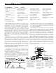
Warning Symbol This symbol calls attention to an operating procedure, practice, or the like which, if not correctly performed or adhered to, could result in personal injury or damage to or destruction of part or all of the product and system. Do not proceed beyond a warning symbol until the indicated conditions are fully understood and met. Using the Manual Installers . . . . . . . . . . . . . . . . . . . . . . . . . . . Read Chapters 1, 2 Basic Function User . . . . . . . . . . . . . . . .
NOTES
Chapter 1 Overview 1–1 Features ** Unique * Valuable * Automatic programming ** High accuracy 18-bit input A–D * Differential control ** High accuracy 15-bit out* Auto-tune function put D–A * Self-tune function ** Fast input sample rate (5 * Sleep mode function times/second) * “Soft-start” ramp and dwell ** Two function complexity timer levels * Programmable inputs (ther** User menu configurable mocouple, RTD, mA, VDC) ** Pump control * Analog input for remote set * Fuzzy plus PID micropoint and CT proce
1–2 Ordering Code TEC-9300Power Input 1 2 3 5 4 6 4: 90 - 264 VAC, 50/60 HZ 5: 11 - 26 VAC or VDC 9: Special Order Alarm 1 Signal Input 1: Standard Input Input 1 - Universal Input Thermocouple: J, K, T, E, B, R, S, N, L RTD: PT100 DIN, PT100 JIS Current: 4 - 20mA, 0 - 20 mA. Voltage: 0 - 1V, 0 - 5V, 1 - 5V, 0 - 10V Input 2 - CT and Analog Input CT: 0 - 50 Amp. AC Current Transformer Analog Input: 4 - 20 mA, 0 - 20mA, 0 - 1V, 0 - 5V, 1 - 5V, 0 - 10V.
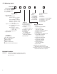
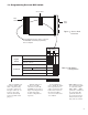
1–3 Programming Port and DIP Switch Access Hole Front Panel 1 2 3 4 ON DIP Rear Terminal Figure 1.. Access Hole Overview The programming port is used to connect to the TEC99001 for instant programming from a computer DIP Switch :ON 1 2 :OFF 3 4 T C, R T D , mV Input 1 Select 0-1V, 0-5V, 1-5V, 0-10V 0-20 mA , 4-20 mA A ll pa ra me te rs a re Unlocke d * Only SP1, SEL1 SEL5 a re unl oc ke d Lockout O nly S P 1 is unlocke d Table 1.
1–4 Keys and Displays The unit is programmed by using the three keys on the front panel. The available key functions are listed in the following table.
1–4 Keys and Displays continued… 5
1–5 Menu Overview 6
1–6 System Modes The controller performs closed loop control in its normal control mode condition. The controller will maintain its normal control mode when you are operating the user menu, setup menu, display mode, reloading default values, or applying event input signals. Under certain conditions, the normal control mode will transfer to an exception mode. The exception modes include: sleep mode, manual mode, failure mode, calibration mode, and auto-tuning mode.
1–7 Parameter Description NOTE: For RS-232: Short J1, Open/Cut J2 Using RS-232 will disable Event Input Function 8
9
10
11
12
Note: Calibration menu is for supplier configuration use only.
14
Chapter 2 Installation Dangerous voltage capable of causing death can be present in this instrument. Before installation or beginning any troubleshooting procedures, the power to all equipment must be switched off and isolated. Units suspected of being faulty must be disconnected and removed to a properly equipped workshop for testing and repair. Component replacement and internal adjustments must be made by a qualified maintenance person only.
2–4 Power Wiring The controller is supplied to operate at 11–26VAC/VDC or 90–264VAC. Check that the installation voltage corresponds to the power rating indicated on the product label before connecting power to the controller . This equipment is designed for installation in an enclosure which provides adequate protection against electrical shock. The enclosure must be connected to earth ground. Local requirements regarding electrical installation should be rigidly observed.
2–7 RTD Input Wiring The RTD connections are shown in figure 2.6, with the compensating lead connected to terminal 12. For two-wire RTD inputs, terminals 12 and 13 should be linked. A three-wire RTD offers the capability of lead resistance compensation, provided that the three leads are the same gauge and equal in length. For the purpose of accuracy, two-wire RTD should be avoided, if possible. A 0.4 ohm lead resistance in a two-wire RTD will produce 1°C temperature error.
2–9 CT/Heater Current Input Wiring Make sure that the total current through TEC99999 does not exceed 100A rms in a 3-Phase system.
2–10 Event Input wiring The event input can accept a switch signal as well as an open collector signal. The event input function (EIFN) is activated when the switch is closed or an open collector (or a logic signal) is pulled down. Also refer to section 4-1 for event input functions.
2–11 Output 1 Wiring 20
2–12 Output 2 Wiring 21
2–13, 2–14 Alarm 1 and 2 Wiring Note: Both Form A and B contacts are available for the alarm 1 relay. Order the correct form for alarm 1 to suit your needs.
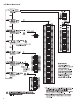
2–15 RS-485 1 2 3 4 5 6 7 8 Figure 2.18 RS-485 Wiring RS-485 to RS-232 network adaptor 9 10 11 12 13 14 15 16 TX2 TX1 TEC99001 RS-232 RS-485 TX1 Twisted-Pair Wire 1 9 2 3 10 11 TX1 4 5 6 7 TX2 PC 8 12 13 14 15 16 TX2 Max. 247 units can be linked 1 9 TX1 2 3 10 11 4 5 6 7 8 12 13 14 15 16 TX2 Terminator 220 ohms / 0.
2–16 RS-232 Figure 2.19 RS-232 Wiring TEC99014 Figure 2.20 Location of Jumper JP22 Figure 2.21 Configuration of RS-232 Cable If you use a conventional 9-pin RS-232 cable instead of TEC99014, the cable must be modified according to the circuit diagram above. 24 Note: If the TEC-9300 is configured for RS-232 communication, the EI (event input) is disconnected internally. The unit can no longer perform event input function (EIFN).
Chapter 3 Programming Basic Functions This unit provides a useful parameter “FUNC” which can be used to select the function complexity level before setup. If Basic Mode (FUNC=BASC) is selected for a simple application, then the following functions are ignored and deleted from the full function menu: RAMP, SP2, PB2, TI2, TD2, PL1, PL2, COMM, PROT, ADDR, BAUD, DATA, PARI, STOP, AOFN, AOLO, AOHI, IN2, IN2U, DP2, IN2L, IN2H, EIFN, PVMD, FILT, SLEP, SPMD, and SP2F. Basic Mode capabilities: 1. 2. 3. 4. 5. 6.
3–2 OUT1 and OUT2 Types O1TY: Selects the signal type for Output 1. The selection should be consistent with the output 1 module installed.
3–4 Heat Only Control continued… The ON-OFF control may introduce excessive process oscillation even if hysteresis is minimized to the smallest. If ON-OFF control is set (i.e., PB1=0), TI1, TD1, CYC1, OFST, CPB and PL1 will be hidden and have no function to the system. The manual mode, auto-tuning, self-tuning and bumpless transfer will be disabled too.
3–6 Heat-Cool Control The heat-cool control can use one of six combinations of control modes. Setup of parameters for each control mode are shown in the following table. NOTE: The ON-OFF control may result in excessive overshoot and undershoot problems in the process. The P (or PD) control will result in a deviation process value from the set point. It is recommended to use PID control for the heat-cool control to produce a stable and zero offset process value.
3–7 Dwell Timer Alarm 1 or alarm 2 can be configured as dwell timer by selectError Code ing TIMR for A1FN or A2FN, but not both, otherwise Er07 will appear. As the dwell timer is configured, the parameter TIME is used for dwell time adjustment. The dwell time is measured in minute ranging from 0 to 6553.5 minutes. Once the process reaches the set point the dwell timer starts to count from zero until time out.The timer relay will remain unchanged until time out.
3–8 Process Alarms There are at most two independent alarms available by adjusting OUT2. If AL2 is selected for OUT2, then OUT2 will perform alarm 2 function. Now NONE can’t be selected for A2FN, otherwise Er06 will be displayed. A process alarm sets an absolute trigger level (or temperature). When the process (could be PV1, PV 2, or PV1PV2) exceeds that absolute trigger level, an alarm occurs. A process alarm is independent from the set point. Adjust A1FN (Alarm 1 function) in the setup menu.
3–9 Deviation Alarm OUT2 can be configured as alarm 2 by selecting AL2. If AL2 is selected for OUT2, then output 2 will perform alarm 2 function. Now NONE can’t be selected for A2FN, otherwise Er06 will appear. A deviation alarm alerts the user when the process deviates too far from the set point. The user can enter a positive or negative deviation value (A1DV, A2DV) for alarm 1 and alarm 2. A hysteresis value (A1HY or A2HY) can be selected to avoid interference problems in a noisy environment.
3–10 Deviation Band Alarm A deviation band alarm presets two reference levels relative to set point. Two types of deviation band alarm can be configured for alarm 1 and alarm 2. These are deviation band high alarm (A1FN or A2FN select DB.HI) and deviation band low alarm (A1FN or A2FN select DB.LO). A1SP and A1HY are hidden if alarm 1 is selected as a deviation band alarm. Similarly, A2SP and A2HY are hidden if alarm 2 is selected as a deviation band alarm.
3–11 Heater Break Alarm A current transformer (Part No. TEC99999) should be installed to detect the heater current if a heater break alarm is required. The CT signal is sent to input 2, and the PV2 will indicate the heater current in 0.1amp resolution. The range of the current transformer is 0 to 50.0amp. For more detailed descriptions about heater current monitoring, please see section 3-24. Heater break alarm 1 Setup: IN2=CT A1FN=PV2.L A1MD=NORM A1HY=0.
3–13 Sensor Break Alarm Alarm 1 or alarm 2 can be configured as a sensor break alarm by selecting SENB for A1FN or A2FN. If alarm 2 is required as a sensor break alarm, then AL2 should be selected for OUT2. The sensor break alarm is activated as soon as failure mode occurs. Refer to section 3-16 for failure mode conditions. Note that A-D failure also creates a sensor break alarm. TIME, A1SP, A1DV, and A1HY are hidden if alarm 1 is configured as a sensor break alarm.
3–16 Failure Transfer The controller will enter failure mode if one of the following conditions occurs: 1. SB1E occurs (due to input 1 sensor break or input 1 current below 1mA if 4–20mA is selected or input 1 voltage below 0.25V if 1–5V is selected) if PV1, P1-2, or P2-1 is selected for PVMD or PV1 is selected for SPMD. 2. SB2E occurs (due to input 2 sensor break or input 2 current below 1mA if 4–20mA is selected or input 2 voltage below 0.
3–17 Bumpless Transfer The bumpless transfer function is Bumpless transfer available for output 1 and output 2 setup: (provided that OUT2 is configured 1. O1FT = BPLS as COOL). 2. O2FT = BPLS Bumpless transfer is enabled by selecting BPLS for O1FT and/or Bumpless transfer O2FT and activated as one of the occurs as: following cases occurs: 1. Power starts (within 1. Power starts (within 2.5 seconds). 2.5 seconds) 2. The controller enters failure 2. Failure mode is actimode.
3–19 Auto tuning The auto-tuning process is performed at the set point. The process will oscillate around the set point during the tuning process. Set the set point to a lower value if overshooting beyond the normal process value is likely to cause damage.
3–20 Manual Tuning In certain applications (very few), when using both self-tuning and auto-tuning to tune a process proves inadequate for the control requirements, you can try manual tuning. Connect the controller to the process and perform the procedures according to the flow chart shown in the following diagram. If the control performance using auto or selftuning is still unsatisfactory, the following rules can be applied for further adjustment of PID values: Figure 3.
3–21 Signal Conditioner DC Power Supply Three types of isolated DC power supplies are available to supply an external transmitter or sensor. These are 20V rated at 25mA, 12V rated at 40mA and 5V rated at 80mA. The DC voltage is delivered to the output 2 terminals. 3–22 Manual Control Manual control may be used for the following purposes: 1. To test the process characteristics to obtain a step response as well as an impulse response and use these data for tuning a controller. 2.
3–23 Display Mode Operation Press several times until (display) appears on the display. Then press to enter display mode. You can select more parameters to view by pressing or pressing in reverse sequence. The system mode of the controller and its operation will remain unchanged. When the controller enters display mode, the upper display will show the parameter value and the lower display will show the parameter symbol except and shows the percent.
Chapter 4 Full Function Programming 4–1 Event Input Refer to section 2-10 for wiring an event input. The event input accepts a digital type signal. Three types of signal, relay or switch contacts, open collector pull low, and TTL logic level can be used to switch the event input. One of ten functions can be chosen by using (EIFN) in the setup menu. NONE: Event input no function If chosen, the event input function is disabled.
4–3 Second PID Set In certain applications the characteristics of a process are strongly related to its process value. The TEC9300 provides two sets of PID values. When the process is changed to a different set point, the PID values can be switched to another set to achieve optimum conditions. Application 1: programmed by the set point Apply Signal To 14 13 Event input + Event input – Setup EIFN choose PID2 or The optimal PID values for a SP.P2 process may vary with its process value and set point.
4–4 Ramp and Dwell, continued… Ramp and dwell A ramp may be accompanied with a dwell timer to control the process. Here is an example. Example with ramp and dwell Select HRR for SPMD, PU for IN1U, 2-DP for DP1, and set RAMP=60.00. Select TIMR for A2FN and set TIME=20.0. Set E1 for SP2. When power is applied, the process value starts at 0.00, SP1=30.00, and SP2=40.00. The timer output is used to control event input.
4–7 Output Power Limits In certain systems the heater (or cooler) is overMenu designed such that the process is too heavily heated PL1 or cooled. To avoid an excessive overshoot and/or PL2 undershoot you can use the power limit function. Output 1 power limit PL1 is contained in the user menu. If output 2 is not used for cooling (that is, COOL is not selected for OUT2), then PL2 is hidden. If the controller is used for ON-OFF control, then both PL1 and PL2 are hidden.
4–9 Analog Retransmission Analog retransmission is available for model number TEC-9300-XXXXXN where N=3, 4 or 5. See ordering code in section 1-2. 4–10 Digital Filter Setup Menu Setup Menu FUNC COMM Setup AOFN Select FULL for FUNC in the setup menu. AOLO Select a correct output signal for COMM which should be accordant with the AOHI Terminals retransmission option used. Five types of retransmission output are available. These Terminals 9 AO+ are: 4–20mA, 0–20mA, 0–5V, 1–5V and 9 AO+ 0–10V.
4–12 Pump Control Pump control function is one of the PUMP: unique features of the TEC-9300. A cost effective solution Using this function, the pressure in a process can be excellently controlled. The pressure in a process is commonly generated by a pump driven by a variable speed motor. The complete system has the following characteristics which affect control behavior. 1. The system is very noisy. 2. The pressure changes very rapidly. 3.
Chapter 5 Applications 5–1 Pump/Pressure Control Regulated water supply systems are widely used in residential areas, water plants, chemical plants, electrical plants, semiconductor plants, etc. By taking advantage of its PUMP function, the TEC-9300 can be used to create an economical yet versatile solution for these applications. Here is an example: The water pressure in this example must be controlled at 10Kg/cm≈.
5–2 Variable Period Full Wave SSR, continued… The advantages of VPFW SSR, over conventional SSR, are summarized in the following table: 5–3 Heat Only Control An oven is designed to dry the products at 150°C for 30 minutes and then stay unpowered for another batch. A TEC-9300 equipped with dwell timer is used for this purpose. The system diagram is shown as follows: Output 1 and output 2 of the TEC-9300 can be connected to the VPFW SSR directly provided that a pulsed voltage drive output is ordered.
5–4 Cool Only Control A TEC-9300 is used to control a refrigerator with the temperature below 0°C. To avoid set point adjustment beyond the desired range, SP1L is set at -10°C and SP1H is set at 0°C. Because the temperature is lower than the ambient, a cooling action is required, so select DIRT for OUT1. Since output 1 is used to drive a magnetic contactor, select RELY for O1TY. Because a small temperature oscillation is tolerable, use ON-OFF control to reduce the overall cost.
5–6 Ramp and Dwell Example 1: Temperature cycling chamber A chamber is used to test the temperature cycling effect on personal computers. An external cycle timer is used to control the event input for switching the set point. The products under test are required to stay at 60°C for 1 hour and -10°C for 30 minutes. The transition interval between the high and low temperatures is required to be 5 minutes. Make the following setup: EIFN = SP.
5–7 Remote Set Point An on-line multiple zone oven is used to dry paint. Since heat demand varies at different positions in the production line, multiple zones with individual controls should be used to ensure a consistent temperature profile. If you order a TEC-9300 with a retransmission unit for the master controller, and retransmit its set point to input 2 on the rest of the slave controllers, each zone will be synchronized with the same temperature.
5–9 Dual Set Point/PID The TEC-9300 will switch between the two PID sets based on the process value, the set point, or either of the event inputs. As the control ramps up to the higher process value, the process characteristics change. When this happens, the original PID values are no longer valid. To achieve optimal control over the entire range, a second PID set is used. Example 1: Single set point/dual PID A heat treating furnace is used over the range of 400°C to 1200°C. 1.
5–10 RS-485 A tile making plant has five production lines. Each production line is equipped with 16 TEC-9300 units to control the temperature for the kiln. They want to program the controllers and monitor the process from the control room to improve quality and productivity. A cost-effective solution for the above application would be to use 80 TEC-9300 units plus an SNA10B smart network adapter and BCNet PC-based software for this purpose. The system is installed as shown in the following diagram.
5–11 RS-232 Suppose a chemical experiment is performed in a laboratory and an engineer wants to find the relationship between the chemical reaction and temperature. He uses a TEC-9300 to control the temperature of the solution being tested. He is particularly interested in generating a test report containing the relationship between the concentration and temperature. For a single unit application, it is adequate to order a TEC9300 with RS-232 communication and BC-Net software.
Chapter 6 Calibration Do not proceed through this section unless there is a definite need to recalibrate the controller. If you do recalibrate, all previous calibration data will be lost. Do not attempt recalibration unless you have the appropriate calibration equipment. If the calibration data is lost, you will need to return the controller to your supplier who may charge you a service fee to recalibrate the controller. Entering calibration mode will break the control loop.
Manual calibration procedures, continued… Step 8 Press the scroll key until the display shows . Send a 10V signal to terminals 15 and 16 with the correct polarity. Press the scroll key for at least 3 seconds. The display will blink for a moment until a new value is obtained. If the display didn’t blink or if the obtained value is equal to -199.9 or 199.9, then calibration failed. • Perform step 9 to calibrate mA function ( if required ) for input 2. Step 9 Press the scroll key until the display shows .
Chapter 7 Error Codes and Troubleshooting This procedure requires access to the circuitry of a unit under live power. Accidental contact with line voltage is possible. Only qualified personnel should perform these procedures. Potentially lethal voltages are present. Troubleshooting procedures: 1. If an error message is displayed, refer to table 7.1 to see what caused it and what action to take to correct the problem. 2. Check each point listed below.
58
59
NOTES 60
Chapter 8 Specifications Power 90–264VAC, 47–63Hz, 15VA, 7W maximum 11–26 VAC/VDC, 15VA, 7W maximum Input 1 resolution: 18 bits Sampling rate: 5x/second Maximum rating: -2VDC minimum, 12VDC maximum (1 minute for mA input) Temperature effect: ±1.5uV/°C for all inputs except mA input ±3.0uV/°C for mA input Sensor lead resistance effect: T/C: 0.2uV/ohm 3-wire RTD: 2.6°C/ohm of resistance difference of two leads 2-wire RTD: 2.
Triac (SSR) Output Rating: 1A/240VAC Inrush Current: 20A for 1 cycle Min. Load Current: 50mA rms Max. Off-state Leakage: 3mA rms Max. On-state Voltage: 1.5V rms Insulation Resistance: 1000Mohms min. at 500VDC Dielectric Strength: 2500VAC for 1 minute DC voltage supply characteristics (installed at output 2) Alarm 1/Alarm 2 Alarm 1 relay: Form A or Form B, max. rating 2A/240VAC, 100,000 life cycles for resistive load. Alarm 2 relay: Form A, max. rating 2A/240VAC, 200,000 life cycles for resistive load.
Chapter 9 Modbus Communications This chapter specifies the Modbus Communications protocol as RS-232 or RS-485 interface module is installed. Only RTU mode is supported. Data is transmitted as eight-bit binary bytes with 1 start bit, 1 stop bit and optional parity checking (None, Even or Odd). Baud rate may be set to 2400, 4800, 9600, 14400, 19200, 28800 and 38400. 9-1 Functions Supported Only function 03, 06 and 16 are available for this series of controllers.
9-2 Exception Responses If the controller receives a message which contains a corrupted character (parity check error, framing error, etc.), or if the CRC16 check fails, the controller ignores the message.
9-3 Parameter Table 65
66
67
68
69
70
71
72
73
74
75
9-3 Communication Examples 07 P= 100.
A–1 Menu Existence Conditions 77
78
79
A–2 Factory Menu Description 80
A–3 Glossary Absolute zero: The lowest theoretical temperature. At absolute zero, a body would have no molecular motion of heat energy. Absolute zero is the zero point on the Rankine and Kelvin scales. (-273.15°C or 459.67°F) AC: Alternating Current; an electric current that reverses direction at regularly occurring intervals. Accuracy Calibration accuracy: The potential error of a device compared to a physical constant or agency standard. Control accuracy: Maintaining a process at the desired setting.
Current proportioning: A 4–20 milliamp (typical) current output which provides a current proportional to the amount of control required. Current transformer: A transformer, intended for measuring purposes, designed to generate a current at its secondary winding which is proportional to the current at the primary winding. Cycle time: The time, usually expressed in seconds, for a controller to complete one on/off cycle. Data logging: Recording a process variable over an extended period of time.
Intrinsically safe: An instrument which will not produce any spark or thermal effects under normal or abnormal conditions that will ignite a specified gas mixture. IPTS-68: International Practical Temperature Scale of 1968. Fixed points in thermometry set by the 1968 General Conference of Weights and Measures. ISA: Instrument Society of America. ISE: Integrated squared error Isolation: Electrical separation Isothermal: A process or area that maintains a constant temperature.
Proportional control mode: When process temperature approaches set point and enters the proportional band, the output is switched on and off at the established cycle time. The change in power to the load provides a throttling action which results in less temperature overshoot. Ramp: A programmed rise or fail in temperature at a constant rate. Range: An area between two limits in which a measurement or control action takes place. Typically expressed in upper and lower limits.
A–4 Memohe following table as a master copy for your settings.
86
A–5 Warranty WARRANTY Tempco Electric Heater Corporation is pleased to offer suggestions on the use of its products. However, Tempco makes no warranties or representations of any sort regarding the fitness for use, or the application of its products by the Purchaser. The selection, application, or use of Tempco products is the Purchaser's responsibility. No claims will be allowed for any damages or losses, whether direct, indirect, incidental, special, or consequential.
Complete Your Thermal Loop System With Over 100,000 Various Items Available from Stock • Electric Heating Elements • Videographic Data Recorders • Thermocouples and RTD Assemblies • Temperature Measurement • SCR Power Controls • Current Indicators • Solid State Relays • Thermocouple and Power Lead Wire • Mechanical Relays • Wiring Accessories TEMPCO’s Visionary Solutions ™ The Electric Heating Element, Temperature Controls and Temperature Sensors Handbook REQUEST YOUR FREE 960 PAGE COPY TODAY! C