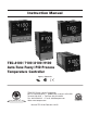
Instruction Manual TEC-4100 / 7100 / 8100 / 9100 Auto-Tune Fuzzy / PID Process Temperature Controller Agency Approvals Serving Industry Since 1972 TEMPCO Electric Heater Corporation 607 N. Central Avenue • Wood Dale, IL 60191-1452 USA Tel: 630-350-2252 • Toll Free: 800-323-6859 Fax: 630-350-0232 • E-mail: info@tempco.com Web: www.tempco.
NOTES
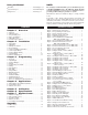
Using the Manual Installers . . . . . . . . . . . . . . . . . . . . . . . . . . . Read Chapter 1, 2 System Designer . . . . . . . . . . . . . . . . . . . . . Read All Chapters Expert User . . . . . . . . . . . . . . . . . . . . . . . . . Read Page 11 CONTENTS Chapter 1 Overview Chapter 2 Installation Chapter 3 Programming Chapter 4 Applications Chapter 5 Chapter 6 Chapter 7 Calibration . . . . . . . . . . . . . . . 21 Specifications . . . . . . . . . . . 23 Modbus Comm. . . . . . . . . . .
NOTES
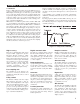
Chapter 1 Overview 1–1 General Tempco’s TEC-x100 Series Fuzzy Logic plus PID microprocessor-based controllers incorporate two bright easy to read 4-digit LED displays, indicating process value and set point value. The process value (PV) display is always the top digital display. The setpoint (SV) display is always the bottom display. Fuzzy Logic technology enables a process to reach a predetermined set point in the shortest time with a minimum of overshoot during powerup or external load disturbance.
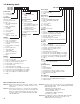
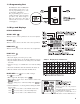
1–2 Ordering Code TEC-4100TEC-7100TEC-8100Alarm Power Input 0 = None 4 = 90-250 VAC 1 = Relay: 2A/240 VAC, 5 = 11-26 VAC/VDC SPDT 9 = Other 9 = Other Signal Input Communication Universal, can be 0 = None programmed in the field 1 = RS-485 Interface for item 5 or 6 2 = RS-232 Interface 5 = TC: *J,K,T,E,B,R,S,N,L (not available for TEC-7100) 0-60 mV 3 = Retransmission 4-20 mA 6 = RTD: *PT100 DIN, (default), 0-20 mA PT100 JIS 4 = Retransmission 1-5 Vdc 7 = 0-1 VDC (default), 0-5 VDC 8 = *0-5, 1-5 VDC 5 = Retra
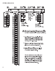
1–3 Programming Port The TEC99011 cable and TEC99003 network adapter can be used to connect the programming port to a PC for automatic configuration. The programming port is used for off-line automatic setup and testing procedures only. Don't attempt to make any connection to these pins when the unit is used for a normal control purpose. 1–4 Keys and Displays KEYPAD OPERATION SCROLL KEY: This key is used to select a parameter to be viewed or adjusted.
1–5 Menu Overview 4
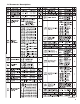
1–6 Parameter Descriptions Continued… 5
Parameter Descriptions, Continued… 6
Chapter 2 Installation Dangerous voltages capable of causing death are sometimes present in this instrument. Before installation or beginning any troubleshooting procedures, the power to all equipment must be switched off and isolated. Units suspected of being faulty must be disconnected and removed to a properly equipped workshop for testing and repair. Component replacement and internal adjustments must be made by a qualified maintenance person only.
2–3 Wiring Precautions Before wiring, verify the correct model number and options on the label. Switch off the power while checking. Care must be taken to ensure that the maximum voltage rating specified on the label is not exceeded. It is recommended that the power for these units be protected by fuses or circuit breakers rated at the minimum value possible. All units should be installed inside a suitably grounded metal enclosure to prevent live parts from being accessible to human hands and metal tools.
2–4 Power Wiring The controller is designed to operate at 11–26 VAC/VDC or 90–250 VAC. Check that the installation voltage corresponds to the power rating indicated on the product label before connecting power to the controller. The controller power input should be equipped with a fuse and switch as shown below in figure 2.7 2–5 Sensor Installation Guidelines Proper sensor installation can eliminate many problems in a control system.
Control Output Wiring, continued… 10
2–8 Alarm Wiring 2–9 Data Communication If you use a conventional 9-pin RS-232 cable instead of TEC 99014, the cable must be modified according to the following circuit diagram.
Chapter 3 Programming Press for 5 seconds and release to enter the setup menu. Press to select the desired parameter. The upper display indicates the parameter symbol, and the lower display indicates the selected value of the parameter. 3–1 Lockout There are four security levels that can be selected using the LOCK parameter. If NONE is selected for LOCK, then no parameter is locked. If SET is selected for LOCK, then all setup data are locked.
Control Outputs, continued… Heat only ON-OFF control: Select REVR for OUT1. Set PB (proportional band) to 0. O1HY is used to adjust dead band for ON-OFF control. The output 1 hysteresis (O1HY) is enabled in case PB=0. The heat only on-off control function is shown in the following diagram: The ON-OFF control may introduce excessive process oscillation even if hysteresis is minimized. If ON-OFF control is set (i.e.
3.3 & 3.4 Alarm Figures Figure 3.3 Output 2 Deviation High Alarm 3–4 Alarm The controller has one alarm output. There are six types of alarm functions and one dwell timer that can be selected, and four kinds of alarm modes (ALMD) are available for each alarm function (ALFN). Output 2 can be configured as another alarm in addition to the alarm output. But output 2 only provides four kinds of alarm functions and only normal alarm mode is available for this alarm.
3–5 Configuring User Menu Most conventional controllers are designed with a fixed order in which the parameters scroll. The x100 series have the flexibility to allow you to select those parameters which are most significant to you and put these parameters at the front of the display sequence. SEL1~SEL8: Selects the parameter for view and change in the user menu.
3–8 PV Shift In certain applications it is desirable to shift the controller display value (PV) from its actual value. This can easily be accomplished by using the PV shift function. The SHIF function will alter PV only. Example: A process is equipped with a heater, a sensor, and a subject to be warmed up. Due to the design and position of the components in the system, the sensor could not be placed any closer to the part.
3–11 Auto-tuning The auto-tuning process is performed near the set point. The process will oscillate around the set point during the tuning process. Set the set point at a lower value if overshooting beyond the normal process value is likely to cause damage. Auto-tuning is applied in cases of: • Initial setup for a new process • The set point is changed substantially from the previous auto-tuning value • The control result is unsatisfactory Operation: 1. The system has been installed normally. 2.
3–13 Manual Control Operation To enable manual control, the LOCK parameter should be set to NONE, then press for 6.2 seconds; (hand control) will appear on the display. Press for 5 seconds, then the MAN indicator will begin to flash and the lower display will show . The controller is now in manual control mode. indicates output control variable for output 1, and indicates control variable for output 2. Now you can use the up and down keys to adjust the percentage values for the heating or cooling output.
Chapter 4 Applications 4–1 Heat Only Control with Dwell Timer An oven is designed to dry products at 150°C for 30 minutes and then stay unpowered for another batch. A TEC8100 equipped with dwell timer is used for this purpose. The system diagram is shown as follows: To achieve this function, set the following parameters in the setup menu: INPT=K_TC UNIT=°C DP=1_DP OUT1=REVR O1TY=RELY CYC1=18.0 O1FT=0.0 ALFN=TIMR ALFT=ON Auto-tuning is performed at 150°C for this application.
4–3 Heat-Cool Control An injection mold is required to be controlled at 120°C to ensure a consistent quality for the parts. An oil pipe is buried in the mold. Since plastics are injected at a higher temperature (e.g., 250°C), the circulation oil needs to be cooled as its temperature rises. Here is an example: The PID heat-cool is used for the example at left. To achieve this, set the following parameters in the setup menu: INPT=PT.DN UNIT=°C DP= 1-DP OUT1=REVR O1TY=RELY CYC1=18.0 (sec.) O1FT=0.
Chapter 5 Calibration Do not proceed through this section unless there is a definite need to recalibrate the controller. If you recalibrate, all previous calibration data will be lost. Do not attempt recalibration unless you have the appropriate calibration equipment. If the calibration data is lost, you will need to return the controller to your supplier who may charge you a service fee to recalibrate the controller. Entering calibration mode will break the control loop.
Manual Calibration Procedures… Set up the equipment according to the diagram above for calibrating the cold junction compensation. Note that a K type thermocouple must be used. The 5520A calibrator is configured as K type thermocouple output with internal compensation. Send a 0.00°C signal to the unit under calibration. The unit under calibration is powered in a still-air room with temperature 25±3°C. Wait at least 20 minutes for warming up.
Chapter 6 Specifications Power 90–250 VAC, 47–63 Hz, 12VA, 5W maximum 11–26VAC/VDC, 12VA, 5W maximum Input Resolution: 18 bits Sampling rate: 5 samples / second Maximum rating: –2VDC minimum, 12VDC maximum (1 minute for mA input) ±1.5uV/°C for all inputs except mA input ±3.0uV/°C for mA input Temperature effect: T/C: 0.2uV/ohm 3-wire RTD: 2.6°C/ohm of resistance difference of two leads 2-wire RTD: 2.
Alarm Alarm relay: Form C 2A/240VAC, 200,000 life cycles for resistive load. Alarm functions: Dwell timer Deviation high/low alarm Deviation band high/low alarm PV high/low alarm Alarm modes: Normal, latching, hold, latching/hold. Dwell timer: 0.1–4553.6 minutes Data Communication Interface: RS-232 (1 unit), RS-485 (up to 247 units) Protocol: Modbus protocol RTU mode Address: 1–247 Baud rate: 2.4–38.
Chapter 7 Modbus Communications This chapter specifies the Modbus Communications protocol as RS-232 or RS-485 interface module is installed. Only RTU mode is supported. Data is transmitted as eight-bit binary bytes with 1 start bit, 1 stop bit and optional parity checking (None, Even or Odd). Baud rate may be set to 2400, 4800, 9600, 14400, 19200, 28800 and 38400. 7-1 Functions Supported Only function 03, 06 and 16 are available for this series of controllers.
7-2 Exception Responses If the controller receives a message which contains a corrupted character (parity check error, framing error etc.), or if the CRC16 check fails, the controller ignores the message.
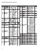
Register Address 33 34 35 36 37 38 39 40 41 42 43 44 45 46 47 48 49 50 51 52 53 54 55 56 57 58 59 60 61 62 63 64, 128 65, 129 66 130 67 131 68 69 70 71, 140 72 73 74 75 76 77 78 79 Parameter Notation ALFN REHI ALMD ALHY ALFT COMM ADDR BAUD DATA PARI STOP SEL1 SEL2 SEL3 SEL4 SEL5 SEL6 SEL7 SEL8 ADLO ADHI RTDL RTDH CJLO CJHI DATE SRNO HOUR BPL1 BPL2 CJCL PV SV MV1 MV2 TIMER EROR MODE PROG CMND JOB1 JOB2 JOB3 CJCT Parameter Alarm Function Retransmission high scale value Alarm operation mode Alarm hysteresis
*1 The error code is shown in the first column of Table A.1 page 32. *2 Definition for the value of MODE register: H’0X00 = Alarm status is off H’000X = Normal mode H’0x01 = Alarm status is on H’010X = Calibration mode H’020X = Auto-tuning mode The alarm status is shown in MV2 instead of H’030X = Manual control mode MODE for models TEC-220 and TEC-920. H’040X = Failure mode *3 The PROG Code is defined in the following table Model No. TEC-9100 TEC-8100 TEC-4100 TEC-7100 TEC-220 TEC-920 PROG Code 6.XX 11.
7-5 Communication Examples: Example 1: Download the default values via the programming port The programming port can perform Modbus communications regardless of the incorrect setup values of address, baud, parity, stop bit, etc. It is especially useful during the first time configuration for the controller. The host must be set with 9600 baud rate, 8 data bits, even parity and 1 stop bit. The Modbus message frame with hexadecimal values is shown as follows: 01 10 00 00 00 34 68 Addr. Func. Starting Addr.
Table A.
WARRANTY Tempco Electric Heater Corporation is pleased to offer suggestions on the use of its products. However, Tempco makes no warranties or representations of any sort regarding the fitness for use, or the application of its products by the Purchaser. The selection, application, or use of Tempco products is the Purchaser's responsibility. No claims will be allowed for any damages or losses, whether direct, indirect, incidental, special, or consequential.
Complete Your Thermal Loop System With Over 100,000 Various Items Available from Stock • Electric Heating Elements • Videographic Data Recorders • Thermocouples and RTD Assemblies • Temperature Measurement • SCR Power Controls • Current Indicators • Solid State Relays • Thermocouple and Power Lead Wire • Mechanical Relays • Wiring Accessories TEMPCO’s Visionary Solutions ™ The Electric Heating Element, Temperature Controls and Temperature Sensors Handbook REQUEST YOUR FREE 960 PAGE COPY TODAY! C