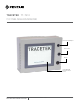
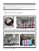
TraceTek TT-TS12 TT-TS12 Panel Installation Instructions Front Panel USB port Door Latch Buzzer 12” Display and Interactive Touch Screen THERMAL BUILDING & INDUSTRIAL HEAT TRACING SOLUTIONS EN-TraceTekTTTS12-IM-H80856 01/15 1 / 16
Description Please read these instructions carefully and keep them in a safe place (preferably close to the TT-TS12-Panel) for future reference. These instructions must be followed carefully to ensure proper operation. The TT-TS12-Panel has been designed specifically for use with TraceTek sensor interface modules and relay modules. See the TT-TS12 Data Sheet H80617 for further information on system capabilities. See the TT-TS12 Operation Manual H80760 for details on system operation.
Installation items (not supplied) • Wall fasteners for surface mounting (four screws) appropriate to the wall surface material • (Optional) TT-TS12 TRIM FLANGE Part Number P000000780 (available for semi-flush mounting of the TT-TS12-Panel) Tools required: • Drills and chassis punch for electrical conduit or cable gland entries into TT-TS12-Panel at desired locations • Center punch • Phillips (cross-head) screwdriver • Small flat-head screwdrivers for terminal block connections • Large flat head screwdriver
Installing the TT-TS12-Panel WARNING: Ignition hazard. Do not mount the TT-TS12-Panel unit in a hazardous location. The TT-TS12-Panel must be in an ordinary area. Choose an office or control room location indoors where the TT-TS12-Panel will be protected from the elements and temperature extremes Note: The TT-TS12-Panel is an electronic unit.
Cable Gland and Conduit Entries The primary cable entry surface is the bottom edge of the TT-TS12-Panel enclosure. Alternate entry points may be appropriate for some installations. It is the responsibility of the installer to note internal clearance and choose standard entry points such that the wire and cable routing do not interfere with the internal components.
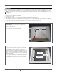
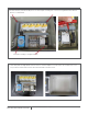
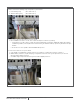
5. Remove four bolts (4 mm Allen head) that secure the back plane assembly to the enclosure. A long handle 4 mm T-bar Allen Wrench is recommended. Back plane assembly securing bolt locations 6. Lift the back plane assembly and wire harness out of the enclosure and place on a clean surface. The TT-TS12 touch screen itself, the buzzer and the USB extension cable remain mounted on the door interior.
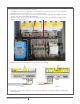
Cable Gland and Conduit Entries There are three categories of cable connections. See Figure 2 for reference. A. Mains power – generally positioned in the lower right corner of the enclosure B. Network connections – (all of the following are optional and may not be relevant for a specific installation). Positioned on right half of enclosure bottom surface a. RS485 twisted pair cable to any external SIM units; TT-NRM relay units; Smart Gateways; RTU radios; Fiber Optic Modem b.
Re-install Back Plane Assembly and Wire Harness 1. Re-install the back plane assembly by reversing the removal procedures. 2. Reinstall the four bolts that secure the back plane assembly. 3. Restore wire harness connectors on back of TT-TS12 touchscreen. 4. Slip wire harness into wire harness holders on door and left side of enclosure. Snap wire harness holders closed. 5.
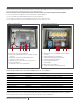
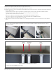
2. Make connections to summary relays if required. See picture below. a. Leak Summary Relay (NO: 1 COM: 2 NC: 3 ) b. Trouble Summary Relay (NO: 4 COM: 5 NC: 6 ) 3. Connections to External SIM Network. See picture below. a. External Modbus slave devices can be connected via twisted pair at terminals 7 (+) and 8 (-) i.
5. Connecting sensor circuit leader cables to internal SIMs a. A maximum of four TTSIM-1 or TTSIM-1A units are installed within the TT-TS12-Panel enclosure. Each TTSIM unit is designed to monitor one sensor cable circuit or one sensor probe circuit. b. Each sensor circuit is connected to the TS12 enclosure with a 4-conductor leader cable. The standard color code for TraceTek leader cables is RED-GREEN-YELLOW-BLACK c.
6. Optional Additional Relay Connections a. TTSIM-1A units have a built in Form-C alarm relay that can be configured to indicate LEAK; LEAK or TROUBLE; or LEAK, SERVICE NEEDED or TROUBLE. The access to these individual relays is via Terminals 10,11 and 12 on each installed TTSIM-1A unit, see below. b. The ADAM-4069 module has 8 relays. The first three of these are pre-assigned for buzzer control, summary LEAK and summary TROUBLE.
ii. Lift the ADAM-4522 module out of the way to expose the ADAM 4069 module beneath. iii. The ADAM-4069 module has 4 available Form-A (SPST) Normally Open relays available and 1 Form-C (SPDT) terminal strips on the top and bottom connector. Relays 4,5 and 6 are Form-A; relay 7 is Form-C iv. The connectors are removable for easier wiring. v. Make relay connections as appropriate. The watchdog signal is between RL3 NO and RL3 COM. vi.
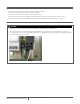
8. Spare USB connection a. One USB port is permanently routed to the USB socket on the front of the TT-TS12-Panel enclosure. The front panel USB port is used for software updates, data base back-up, loading images or temporary connection of a mouse or keyboard during set-up and commissioning. A second USB socket is available on the rear of the TT-TS12 touchscreen and is normally not used. However the second USB port is fully functional and can be used if circumstances require a second USB connection.
Final Inspection: Check for: • No metal filings or other foreign materials present (vacuum or blow out) • Back plane assembly hold down bolts are tight • Mounting hardware tight • Conduit or cable glands tightened • All screw connections at terminal blocks snug (do not over tighten smaller screw terminals) • All wires routed such that the door opens and closes freely • All wire duct covers replaced • Leader cables from sensor circuits identified • Generally neat and organized appearance • Fuses installed in
See the TT-TS12 Operation Manual H80760 for system configuration, set-up and operating instructions.
WWW.PENTAIRTHERMAL.COM NORTH AMERICA Europe, Middle East, Africa Asia Pacific Latin America Tel: +1.800.545.6258 Fax: +1.800.527.5703 Tel: +1.650.216.1526 Fax: +1.650.474.7215 thermal.info@pentair.com Tel: +32.16.213.511 Fax: +32.16.213.603 thermal.info@pentair.com Tel: +86.21.2412.1688 Fax: +86.21.5426.2937 cn.thermal.info@pentair.com Tel.: +1.713.868.4800 Fax: +1.713.868.2333 thermal.info@pentair.com Pentair and TraceTek are owned by Pentair or its global affiliates.