MIT-CAT5 8 and 16 Port KVM User Guide www.ConnectPRO.com North American HQ Walnut, California Asian HQ Taipei, Taiwan Tel: 1 (909) 444 9288 Tel: 886-2-2253-5077 info@ConnectPRO.com asia@ConnectPRO.com support@ConnectPRO.com Vers. 5.03.
Table of Contents 1. Welcome...............................................................................................................3 2. Introduction..........................................................................................................4 3. Features.................................................................................................................4 4. System components...............................................................................................4 5.
2. Control software system requirements..............................................................21 33. Connecting the RS232 Serial cable...................................................................21 34. Installing and running the Control software......................................................21 35. Computer icons..................................................................................................22 36. Communication Error......................................................
interference when operating the equipment in a commercial environment. If operation of this equipment in a residential area causes radio frequency interference, the user, and not ConnectPRO Inc. Limited, will be responsible. Changes or modifications made to this equipment not expressly approved by ConnectPRO Inc. Limited could void the user’s authority to operate the equipment. ConnectPRO Inc. Limited assumes no responsibility for any errors that appear in this document.
2. Introduction Access and control multiple multi-platform computers from one Keyboard Video Mouse (KVM) console with the Multi-Platform CAT5 KVM (CAT5 KVM) system. The CAT5 KVM comes in 8 and 16 port models. Connect up to 8 computers to the 8 port model, and up to 16 to the 16 port model. 3.
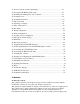
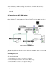
• VGA, SVGA, or XGA monitors • DOS, Windows (3X, 9X, 2000, NT4, ME, XP), LINUX, UNIX, HP UX, QNX, SGI, FreeBSD, BeOS, Open VMS, Novell 3.12-6 6. The CAT5 KVM system configuration Figure 1 illustrates the basic configuration of the CAT5 KVM system. Figure 1 The CAT5 KVM system configuration 7. The CAT5 KVM models Figure 2 illustrates the front panel of the CAT5 KVM 16 port model. The 8 port model is the same but with only 8 rows of LEDs.
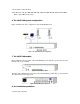
• Place cables away from fluorescent lights, air conditioners, and machines that are likely to generate electrical noise • Ensure that the maximum distance between each computer and the CAT5 KVM, does not exceed 10m/33ft 9. Connecting the CAT5 KVM system Connect each computer to the CAT5 KVM system using the appropriate CIM and CAT5 cables. Figure 4 illustrates the CAT5 KVM system connections with the appropriate CIM connected to a PS/2, SUN and USB computer/server.
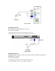
Figure 5 PS/2 CIM Connecting a SUN CIM Figure 6 illustrates the SUN CIM and its connections. To connect the SUN CIM: 1. Connect the Screen connector to the computer’s Video card. 2. Connect the Keyboard connector to the computer’s Keyboard port. Figure 6 SUN CIM Connecting a USB CIM The CIM USB supports Windows 98 SE and later, MAC, SUN and SGI. Figure 7 illustrates the USB CIM and its connections. To connect the USB CIM: 1. Connect the Screen connector to the computer’s Video card. 2.
Figure 7 USB CIM VGA Extender cable Where the CIM’s Screen connector won’t reach the computer’s Video card, connect the VGA Extender cable to the CIM and then follow the instructions below. Connecting the CAT5 cables 1. Connect one connector to the CIMs RJ45 port. 2. Connect the other connector to one of the CAT5 KVM’s Computer ports. 3. Follow the above 2 steps for each computer. Connecting the KVM console To connect a KVM console to the CAT5 KVM: 1.
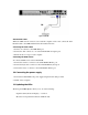
12. Resetting the Switch To reset the Switch press the 2 front panel Select buttons simultaneously. The CIMs are unaffected by this reset. Resetting can also be performed through the software – explained later. 13. Rack mounting the CAT5 KVM Use the L-shaped brackets and screws provided to mount the CAT5 KVM on a server rack as illustrated below. 14. Rack mounting the CIMs You can attach the CIMs to a server rack or computer using the Velcro strips provided. Or connect it using the bracket provided.
Switch between the connected computers by either • The front panel Select buttons • Keyboard hotkeys • The OSD (On Screen Display) The OSD is also the place to adjust various settings as explained below. When switching computers the illuminated LED of the top bank indicates which computer is currently selected. 16. The keyboard hotkeys To switch to the next computer forwards press Shift then, +. Release Shift, before pressing +. To switch to the next computer backwards press Shift then, -.
To select a computer: 1. Navigate to the desired computer line. 2. Press Enter. The selected computer is accessed. An confirmation label appears showing which computer is accessed. Note! When the OSD is displayed you cannot select computers using the front panel Sele ct buttons or the keyboard hotkeys. 20. The OSD settings (F2) Press F2. The OSD Settings window appears see Figure 9.
Administrator (Status A) The Administrator can: • Set and modify all Passwords and security profiles • Fully access any computer • Use all OSD functions Supervisor (Status S) The Supervisor can: • Fully access any computer • Access the following OSD functions only –F4 Scan, F5 Tune and F6 Moving the Confirmation label. User (Status U) There are 6 different Users in the CAT5 KVM system. Each User has a Profile set by the Administrator that defines the access level to different computers.
2. Press the Space bar to toggle between options. To display the OSD in future press the new hotkey. Autoskip With the Autoskip feature, the arrow keys only access the active computer lines on the OSD. When Autoskip is Off, The arrow keys access both active and inactive computer lines. To change the Autoskip setting: 1. Navigate to the Autoskip line. 2. Toggle between the options using the Space bar. Serial port The Serial port is used for the Control Management program.
Figure 11 Ports Settings window Editing the computer name In this window you can edit the computer names with up to 15 characters. To erase a character: Select it and press the Space bar. Blank spaces remain in place of the erased character. To erase an entire line: Place the cursor at the beginning of the line. Keep the Space bar depressed until the line is erased. Keyboard (KB) The CAT5 KVM operates with Windows, Linux, HP UX, Alpha UNIX SGI, DOS, Novell, MAC, USB or Open VMS.
In the Settings window navigate to the Time line and press Enter. The Time settings window appears see Figure 12. Figure 12 Time settings window Scan (SCN) - Label (LBL) - Time out (T/O) SCN SCN column, change the scan period. LBL - In the LBL column, change the display period of the OSD label showing which computer is currently accessed. T/O - When password protection is activated you can automatically disable the Management keyboard, mouse and screen after a preset time of non-use.
Figure 13 The Users settings window There are 3 different access levels. These are: • Y – Full access to a particular computer. Plus access to the F4, F5 and F6 OSD functions • V –Viewing access only, to a particular computer (No keyboard/mouse functionality) • N – No access to a particular computer – A TIMEOUT label appears if access is attempted To give each user the desired access level: 1. Navigate to the desired computer line and User. 2. Toggle between the options using the Space bar. 26.
By default the User Profile settings are full access. 27. The OSD HELP window – F1 To access the HELP window press F1. The HELP window appears, see Figure 15. Figure 15 The HELP window Please note! All the functions set out in the Help window are performed from the Main window. The Help window is merely a reminder of the hotkeys and their functions. 28. Scanning computers– F4 Where necessary adjust the scan time in the Time Settings window, see above. To activate scanning: 1.
3. Adjust the image by using the RightLeft Arrow keys. 4. When the image is satisfactory, press Esc. Note! Picture quality is relative to distance. The further away a remote computer is from the CAT5 KVM, the lower the image quality, and the more tuning needed. So place the higher resolution computers closer to the manager unit. 30. Moving the label – F6 Position the OSD label anywhere on the screen. To position the label from the Main window: 1.
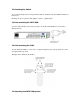
• Free Serial port 33. Connecting the RS232 Serial cable To run the software, connect the RS232 Serial cable to the computer containing the software, and to the CAT5 KVM. See the figure below. Figure 16 Connecting the RS232 Serial cable 34. Installing and running the Control software Note! The CAT5 KVM system must be fully connected BEFORE running the Control software. Failure to first connect the system will lead to the software working in demo mode.
which the RS232 Serial cable is connected. Failure to select the correct Com port will result in the software running in demo mode. Once Setup is complete the Control window appears. See the figure below. Figure 17 The Control window 35. Computer icons Icon Meaning Computer is connected and switched on Computer is switched off or unconnected Connected and switched on computer with a Local . After remaining idle for the Timeout period, it changes to yellow.
37. The View menu From the View menu choose to display: • All computers, or only active switched on computers. • The Legend • The toolbar 38. Selecting a computer To select a computer: Click on the computers icon. The system switches to that computer. The connected icon appears with a red background . Control and monitor the selected computer from the keyboard and mouse connected to the CAT5 KVM. 39. The toolbar buttons The toolbar buttons are explained below. 40.
To change the OSD settings you must press or choose Write Configuration from the File menu after making changes. The changes will then be sent to the CAT5 KVM Manager, and the OSD will reflect these changes. Renaming a computer To rename a computer: 1. Type the new name in the box below the computer icon. 2. Click to send the new name to the CAT5 KVM system. Or click SaveSaveAs from the File menu to save the change in a file and not alter the OSD names. The Edit menu You can edit all OSD fields.
Figure 21 The Settings box Here you can edit all the data that can be edited in the OSD. This includes: Scan times, Confirmation label display time, Timeout, mouse type, keyboard type, User access, password mode, Autoskip mode, keyboard mode – Display hotkey. To edit a setting: 1. Select the desired computer or group of computers. 2. Make the desired changes. 3. Check the Select box next to the changed setting. 4. Click OK.
To view to the factory default settings: From the File menu choose New. 45. Reminder! All changes done with the Control software are only reflected in the OSD AFTER pressing . 46. Password protection When the CAT5 KVM system is password protected, the Control software behaves in exactly the same way as the OSD. You must type in the required password to access the Control software. The access you gain depends on the security status – exactly as with the OSD.
The Administrator defines the desired access levels of each User Profile. This is done in the Setting box. By default the User Profile settings are full access. 47. Upgrading the CAT5 KVM firmware With the CAT5 KVM Update software program you can upgrade the firmware for the: • OSD • Manager • CIMs CAT5 KVM Update enables you to add new features and fix bugs in a quick and efficient manner. You can install the Multi-Platform CAT5 KVM Update on any computer, even one not part of the CAT5 KVM system.
2. Choose Multi-Platform CAT5 KVM Softpack. 3. Either run the Multi-Platform CAT5 KVM Update software straight from the CD or install it on the computer’s hard drive and run it from there. 52. Starting and configuring the CAT5 KVM Update 1. Start the CAT5 KVM Update software. The CAT5 KVM Update window appears. See Figure 23. Figure 23 The Multi-Platform CAT5 KVM Update window The table below explains the functions of the buttons and boxes in the Multi-Platform CAT5 KVM Update window.
See Figure 24. Figure 24 The Com Option box 3. Choose an available Com Port and click OK. Note! The RS232 Serial cable must be connected to the selected Serial port. 53. Verifying the version numbers Before upgrading the firmware, you must first verify which firmware and hardware versions you have. The OSD version number To verify the OSD version number: 1. Open the Multi-Platform CAT5 KVM Update program. 2. In the Switch Unit box, check the OSD option. See Figure 23. 3. Click .
4. Click . The hardware version number appears after the CIM number. When “Not responding” appears, there is no computer connected, or it is switched off. 54. Obtaining new firmware Download the latest firmware for your system from www.ConnectPRO.com 55. Updating the firmware Warning! Never switch off any computer connected to the CAT5 KVM system during the updating process. To update the firmware: 1. Open the Multi-Platform CAT5 KVM Update program. 2.
the mouse fails to work properly. Resetting is done via the Serial port, and avoids the need to shut down the computer. NOTE! The Reset function does not affect the parameters of the unit settings. Resetting the Switch or CIM units To reset the Switch or CIM units: 1. For the Switch, check the Multi-Platform CAT5 KVM option in the Switch Unit box. For the CIMs, check one or more CIMs in the CIM Units box. 2. From the Options menu choose Advanced / Reset. The units reset.
Find Left Ctrl +Alt + F9 Again Left Ctrl + Alt + F2 Undo Left Ctrl + Alt + F4 Copy Left Ctrl + Alt + F6 Paste Left Ctrl + Alt + F8 Cut Left Ctrl + Alt + F10 Help Left Ctrl + Alt + F11 Compose Application key or Left Ctrl + Alt + Keypad * Crescent Scroll Lock Volume Up Left Ctrl + Alt + Keypad – Volume Down Left Ctrl + Alt + Keypad + Mute Left Ctrl + Alt + F12 Sun Left ? key Left Windows key Sun Right ? key Right Windows key Alt-Graph Right Alt or Alt Gr Stop A Left Ctrl + Alt
System RJ45 Local KVM RJ11 HDD15/MinDin6/MiniDin6 Operating temperature 0ºC to 40ºC/32ºF to 104ºF Storage temperature -40ºC to 70ºC/-40ºF to 158ºF Humidity 80% non-condensing relative humidity CIMs PS/2 USB SUN VGA HDD15 HDD15 HDD15 Keyboard/Mouse MiniDin6 USB MiniDin6 System RJ45 RJ45 RJ45 Power From computer’s From USB port From computer’s Connections Product weight 107g Shipping weight 300g Dimensions 91 x 41 x 24mm / 3.58 x 1.61 x 0.