RS-422 AND RS-485 APPLICATIONS EBOOK A Practical Guide to Using RS-422 and RS-485 Serial Interfaces v. 1.
International Headquarters Mfg. Co. Inc. 707 Dayton Road Ottawa, IL 61350 USA Phone: (815) 433-5100 General Fax: (815) 433-5105 Website: www.bb-elec.com European Headquarters Westlink Commercial Park Oranmore, Co. Galway, Ireland Phone: (+353) 91-792444 Fax: (+353) 91-792445 Website: www.bb-elec.
Table of Contents B&B Electronics Manufacturing Ltd. .....................Error! Bookmark not defined. RS-422 and RS-485 Applications eBook ......................................................1 Overview .....................................................................................................5 Assumptions .................................................................................................... 6 What is RS-422/RS-485? ..................................................................
Selecting RS-422 and RS-485 Cabling .......................................................43 Number of Conductors .................................................................................... 43 Shielding ....................................................................................................... 44 Cable Characteristics ....................................................................................... 45 Cable Length vs Data Rate .....................................................
Port Powered Converters ................................................................................. 77 Repeaters ...................................................................................................... 77 Optically Isolated RS-422/485 Devices .............................................................. 79 Sources of Additional Information .............................................................81 Global Engineering .................................................................
Chapter 1 - Overview RS-422 And RS-485 Applications Ebook CHAPTER 1 Overview The purpose of this ebook is to describe the main elements of RS-422 and RS-485 data communications systems. The authors have attempted to cover enough technical details so that personnel will have the necessary information to be successful in designing, modifying or troubleshooting an RS-422 or RS-485 data communication system.
Chapter 1 - Overview RS-422 And RS-485 Applications Ebook Assumptions This writers of this ebook have based the content and level of detail on several assumptions. The first assumption is that the personnel reading and using the information in it will have an understanding of basic electricity and electronics.
Chapter 1 - Overview RS-422 And RS-485 Applications Ebook operate over longer distances at higher bit rates than links using RS232. RS-422's capabilities make it a good choice for extending the distance and speed of point-to-point connections. In situations where data must be communicated over long distances and through electrically noisy areas, RS-422 provides a higher reliability replacement for standards such as RS-232 .
Chapter 1 - Overview RS-422 And RS-485 Applications Ebook RS-485 is used as the basis for many commercial and industrial data communications systems. Industry systems such as PROFIBUS, INTERBUS, and others are built on RS-485 technology. RS-422 was historically used in older Apple computers and printers, and in video editing equipment. Often, end-users build systems themselves using RS-232 to RS422/485 converters, RS-485 smart switches, RS-485 repeaters, and other off-the-shelf products.
Chapter 1 - Overview RS-422 And RS-485 Applications Ebook real data. Characteristics such as the bandwidth and amount of attenuation in the media, the amount and type of noise, and the sensitivity of the receiver to the signal and noise, affect the maximum possible data rate and transmission distance.
Chapter 1 - Overview RS-422 And RS-485 Applications Ebook When the TD line is in the idle state (not transmitting), this voltage is negative (representing a logic 1 or mark). A logic 0 or space is represented by a positive voltage. When transmitting data the voltage alternates between that negative level and a positive level. Typically data pulses are transmitted with a magnitude somewhere between ±5 and ±15 volts.
Chapter 1 - Overview RS-422 And RS-485 Applications Ebook Balanced Data Transmission In a balanced data transmission system the voltage produced by the driver appears across a pair of signal lines. These lines produce complementary (opposite) output signals. When one is low, the other is high, and vice versa.
Chapter 1 - Overview RS-422 And RS-485 Applications Ebook When the driver output voltage is measured differentially, the voltage on the A (-) terminal with respect to the voltage on the B (+) terminal is negative when in the idle state. Typically this voltage is expressed as VAB. RS-422 and RS-485 drivers produce a voltage somewhere between 2 to 6 volts across their A (-) and B (+) output terminals.
Chapter 1 - Overview Note: RS-422 And RS-485 Applications Ebook If all RS-485 drivers on a communications line are tri-stated (high impedance), the outputs are floating and will not measure the voltage shown. Balanced differential line receivers sense the voltage state of the transmission line across the two signal input lines, A (-) and B (+). When VAB is between -200 mV and -6 volts the receiver interprets the signal as a logic 1 or mark.
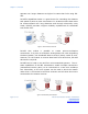
Chapter 1 - Overview RS-422 And RS-485 Applications Ebook Some transceiver chips are manufactured with their driver and receiver data lines connected internally, permanently configuring them as twowire devices. Figure 7: RS-485 Chip with internal bridging The EIA-485 specification labels the data lines A and B. Some manufacturers label two-wire systems DATA A and DATA B and fourwire systems TDA, TDB, RDA and RDB. Other manufacturers simply label them "-" and "+".
Chapter 1 - Overview RS-422 And RS-485 Applications Ebook coupled equally to both signal lines, TDA(-) and TDB(+). At the receiver any signal that occurs equally on both signal lines is subtracted by the differential inputs. This effectively eliminates noise common to both inputs, leaving the communications signal, which can then be detected and recovered.
Chapter 1 - Overview RS-422 And RS-485 Applications Ebook Tri-State Control One important feature of RS-485 systems is the ability to multidrop network nodes. To do so the outputs of all RS-485 drivers not currently transmitting must be effectively disconnected from the transmission line. Without this feature, drivers (which are typically in the idle state when not transmitting), would hold a negative voltage (logic 1 or mark) on the transmission line.
Chapter 1 - Overview RS-422 And RS-485 Applications Ebook third state to the driver output. Because of the three states (logic 0, logic 1 and high impedance) the device output is called a tri-state output. When in the high impedance state the output is sometimes referred to as "tri-stated". In typical systems, control of the driver's enable input is accomplished using RTS Control (on page 17) or Send Data Control (on page 18).
Chapter 1 - Overview RS-422 And RS-485 Applications Ebook Control of the RTS line must be set up in the communications software controlling the serial port, to ensure that the RTS line is asserted before data is applied to the TD line. The RTS line must be unasserted (released) after the last data bit is sent. This not only decouples the driver from the network, but also enables the receiver to accept incoming data put on the communications line by other nodes on the network.
Chapter 1 - Overview RS-422 And RS-485 Applications Ebook One technique for accomplishing this is to use a retriggerable timing circuit, as shown in the following diagram. Figure 11: Send Data Control The timing circuit uses a resistor and capacitor to set the retriggering time constant. The circuit enables the driver when it detects the leading edge of the first data pulse.
Chapter 1 - Overview RS-422 And RS-485 Applications Ebook Care must be taken when setting the period of the timing circuit. If the time is too short, it could time out before the entire character has been transmitted, which would result in retries (the system would repeatedly try to re-send the message). If the time is too long, the start of the data from the last node polled could be lost.
Chapter 1 - Overview RS-422 And RS-485 Applications Ebook NOTE: For a more complete explanation of biasing refer to Biasing an RS-485 Network (p. 32). Figure 12: Bit-Wise Enable Timing For additional details refer to Bit-wise Enable Timing Diagrams (on page 97). Other Tri-State Control Techniques Some RS-485 devices use bit counters or a UART Transmit buffer status line for control.
Chapter 1 - Overview RS-422 And RS-485 Applications Ebook Figure 13: UART Control Page 22 of 137 Manual Documentation Number: www.bb-elec.com/ www.bb-europe.
Chapter 2 - System Configuration RS-422 And RS-485 Applications Ebook CHAPTER 2 System Configuration RS-422 and RS-485 systems can be configured in a variety of ways to provide a wide range of communications solutions. This section includes information on connections and topologies, two and four-wire systems, termination and biasing issues and solutions, and the application of repeaters. 2 In This Chapter RS-422 Point-to-Point Connections ...............................................................
Chapter 2 - System Configuration RS-422 And RS-485 Applications Ebook RS-422 Point-to-Point Connections The most common use for RS-422 devices is in point-to-point serial links where other interface standards such as RS-232 do not provide adequate distance or speed. If the link is simplex (single direction of data flow) a RS-422 system requires a pair of wires for TDA(-) and TDB(+) and a ground.
Chapter 2 - System Configuration RS-422 And RS-485 Applications Ebook Network Topologies The topology of a network describes the physical or logical configuration of the nodes on the network. The EIA standards do not define network topologies for RS-422 and RS-485. A variety of topologies can be used, although in practice some topologies work better than others, for reasons explained in the following sections.
Chapter 2 - System Configuration RS-422 And RS-485 Applications Ebook additional ground conductor should be used to tie the signal grounds together. Note: RS-422/485 systems may communicate successfully without the signal ground when nodes are located close together and circuit grounds for all nodes are at the same potential--e.g., a controlled lab environment. However, this practice is not recommended.
Chapter 2 - System Configuration RS-422 And RS-485 Applications Ebook Four-Wire Systems Like two-wire systems, the name "four-wire" system is something of a misnomer. Four-wire systems should use five conductors for reliable operation in all situations. Typically, four-wire systems implement a master-slave protocol in which the driver of the master is connected by one twisted pair to the receivers of all slaves. Another twisted pair connects the drivers of all slaves to the receiver in the master.
Chapter 2 - System Configuration RS-422 And RS-485 Applications Ebook transmission line, if the line is not terminated with an impedance equal to the line impedance, the transmitted signal is not completely absorbed and a portion is reflected back into the transmission line. Reflections interfere with real data and can cause errors. If the source, transmission line and load impedances are equal, reflections are eliminated.
Chapter 2 - System Configuration RS-422 And RS-485 Applications Ebook Since the receiving UART will sample the data in the middle of the bit, it is important that the signal level be solid at that point. One practical rule of thumb suggests that, for equipment operating data rates less than 38.4 kbps, termination is usually unnecessary.
Chapter 2 - System Configuration RS-422 And RS-485 Applications Ebook Parallel Termination Parallel termination is the addition of a single termination resistor somewhere along the communications line. Ideally termination resistance should be added at the point on the communications line furthest from the driver sending the signal. This works best on a pointto-point link, or an RS-422 four-wire communications system in which a driver at one end sends to a receiver at the other.
Chapter 2 - System Configuration RS-422 And RS-485 Applications Ebook No more than two terminations should be placed in any system that does not use repeaters. Figure 21: Two-Wire Multidrop Network The risk of using bidirectional termination is that it adds heavy DC loading to the system. Port powered RS-232 to RS-485 converters may be overloaded by the use of bidirectional termination.
Chapter 2 - System Configuration RS-422 And RS-485 Applications Ebook AC Termination AC coupled termination adds a small capacitor in series with the termination resistor to eliminate the DC loading effect, which affects biasing. Although this method eliminates DC loading, capacitor selection is highly dependent on the system properties. System designers interested in AC termination are encouraged to read National Semiconductors Application Note 903 (note 2) for further information.
Chapter 2 - System Configuration RS-422 And RS-485 Applications Ebook mV) so that when a driver does start sending serial data the start bit transition (from logic 1 to logic 0) can be detected. However, since all drivers are tri-stated nothing is holding the communication line in the idle state. Without anything driving the network, the state of the line is unknown--essentially floating.
Chapter 2 - System Configuration RS-422 And RS-485 Applications Ebook specifies that a mark is considered anything greater than -200 mV (VAB). To ensure reliable operation B&B Electronics typically suggests that you design for approximately -300 mV. Bias resistors can be placed anywhere in the network, or can be split among multiple nodes. The actual bias resistance is the parallel combination of all bias resistors in a system.
Chapter 2 - System Configuration RS-422 And RS-485 Applications Ebook Current through the voltage divider is approximately 5 mA. The voltage across the signal lines (VAB) is -285 mV. Although slightly less than the goal of -300 mV, this is acceptable for idle state biasing. Figure 24: 10 Node RS-485 Network with two 120 ohm termination resistors Notice that the current is relatively high and the termination resistors are responsible for a majority of the loading.
Chapter 2 - System Configuration RS-422 And RS-485 Applications Ebook Example 2: Biasing when termination resistors are not used In this example, ten RS-485 transceiver nodes are connected together on a daisy-chain network. No termination resistors are connected. Each node includes two built-in 4.7 k biasing resistors, a pull-up and a pulldown. Question: Will this arrangement reliably maintain the idle state when all drivers are tri-stated? RS-485 nodes are specified to present a load impedance of 12 k .
Chapter 2 - System Configuration RS-422 And RS-485 Applications Ebook Current through the voltage divider is approximately 2.23 mA. The voltage across the signal lines (VAB) is -2.7 V. This is much more than the target -300 mV, which ensures good idle state biasing. Figure 25: 10 Node RS-485 Network with no termination resistors Notice that without termination resistors the current requirements are significantly less than when termination resistors are used.
Chapter 2 - System Configuration RS-422 And RS-485 Applications Ebook applications. However, the total current requirement should still be calculated, especially in cases such as when using port-powered converters, which may not be able to supply enough current. Other Biasing and Terminating Considerations Standard RS-485 Biasing Resistors. Most B&B RS-485 equipment includes 4.7 k pull-up and pull-down bias resistors from the factory. This value is adequate for most systems without termination.
Chapter 2 - System Configuration RS-422 And RS-485 Applications Ebook Using Repeaters In some cases a system requires longer communications lines or more nodes than biasing requirements or the EIA/TIA-485 specifications can accommodate. A common, and effective, solution is to use repeaters. An RS-485 repeater can be placed in a system to divide the load into multiple segments. Each "refreshed" signal is capable of driving another 4000 feet of cable and an additional 31 RS-485 loads.
Chapter 2 - System Configuration RS-422 And RS-485 Applications Ebook Using Repeaters in a Master-Slave Network When using repeaters in a master-slave network it can be configured with four-wire on the master side and two-wire on the slave side.
Chapter 2 - System Configuration RS-422 And RS-485 Applications Ebook Using Repeaters in Star, Ring and Tree Networks Repeaters can be used to segment and extend RS-485 networks. As shown in the following diagram, a star configuration can be created by connecting the master node (computer) to several isolated repeaters at a central location. The repeaters connect to nodes on each leg of the star. Each leg can be up to 4000 feet long.
Chapter 2 - System Configuration RS-422 And RS-485 Applications Ebook Using Fractional Load Receivers to Extend Distance and Number of Nodes Another method of increasing the number of RS-485 nodes is to use low (fractional) unit load type RS-485 receivers. These receivers use a higher input impedance to reduce the load on the RS-485 drivers to increase the total number of nodes.
Chapter 3 - Selecting RS-422 and RS-485 Cabling RS-422 And RS-485 Applications Ebook CHAPTER 3 Selecting RS-422 and RS-485 Cabling Cable selection for RS-422 and RS-485 systems is often neglected. Attention to a few details in the selection process can prevent the costly prospect of re-pulling thousands of feet of cable. The EIA-422 specification recommends 24 AWG twisted pair cable with a shunt capacitance of 16 pF per foot and 100 ohm characteristic impedance.
Chapter 3 - Selecting RS-422 and RS-485 Cabling RS-422 And RS-485 Applications Ebook or both conductors for the signal ground. A two-wire system then requires two twisted pairs, and a four-wire system requires three twisted pairs. Figure 30: RS-422 Point-to-Point Connection Shielding It is often difficult to make a clear determination as to whether shielded cable is required in an application or not.
Chapter 3 - Selecting RS-422 and RS-485 Cabling RS-422 And RS-485 Applications Ebook Cable Characteristics When choosing a transmission line for RS-422 or RS-485, it is important to know the total length of the communication cable and the data rate of the system.
Chapter 3 - Selecting RS-422 and RS-485 Cabling RS-422 And RS-485 Applications Ebook approximately 100 kbps. As data rates rise beyond 100 kbps, cable length drops off quickly. For example, at 200 kbps maximum cable length is approximately 1600 feet. At 1 Mbps cable length should not exceed approximately 200 feet. Attenuation vs Frequency Losses in a transmission line are a combination of AC losses (skin effect), DC conductor loss, leakage, and AC losses in the dielectric.
Chapter 3 - Selecting RS-422 and RS-485 Cabling RS-422 And RS-485 Applications Ebook Note 1: Above attenuation data is supplied courtesy Belden Wire and Cable Company Note 2: Datalene is a registered trademark of Belden Wire and Cable Company. Datalene is a type of foamed cellular polyethylene insulation. Using Cat 5 for RS-422/485 There are many cables available that meet the recommendations of EIA-422 and EIA-485. Another choice is the cable used in Ethernet network installations: Category 5 cable.
Chapter 4 - Transient Protection of RS-422 and RS-485 Systems RS-422 And RS-485 Applications Ebook CHAPTER 4 Transient Protection of RS-422 and RS-485 Systems The first step towards protecting an RS-422 or RS-485 system from transients is understanding the nature of the energy we are guarding against. Transient energy may come from several sources, most typically environmental conditions or induced by switching heavy inductive loads. 4 In This Chapter What does a surge look like? ........................
Chapter 4 - Transient Protection of RS-422 and RS-485 Systems RS-422 And RS-485 Applications Ebook Surge Specifications Both of the following specifications provide useful information regarding transients: IEC 1000-4-5: 1995 "Surge Immunity Test" IEEE C62.41-1991 "IEEE Recommended Practice on Surge Voltages in Low-Voltage AC Power Circuits" These documents define the parameters of a 1.2/50µs - 8/20µs combination wave surge. The voltage versus time waveform for this surge has a 1.
Chapter 4 - Transient Protection of RS-422 and RS-485 Systems RS-422 And RS-485 Applications Ebook The specified current waveform for this surge has an 8 µs rise time with a 20 µs decay into a short circuit. Figure 36: Combination Wave Current Waveform Open circuit voltages levels from 1 kV to 6 kV are commonly used in both the positive and negative polarities, although, under some circumstances, voltages as high as 20 kV may be applied. Page 51 of 137 Manual Documentation Number: www.
Chapter 4 - Transient Protection of RS-422 and RS-485 Systems RS-422 And RS-485 Applications Ebook IEEE C62.41 also specifies a 100 kHz "ring wave" test. The ring wave has a 0.5 µs rise time and a decaying oscillation at 100 kHz with source impedance of 12 ohms. Typical amplitudes for the 100 kHz ring wave also range from 1 kV to 6 kV.
Chapter 4 - Transient Protection of RS-422 and RS-485 Systems RS-422 And RS-485 Applications Ebook In some installations, there may be another source of unwanted energy to consider. If there are high voltage cables running anywhere near the data cables, the potential for a fault condition exists as a result of insulation failures or inadvertent contact by an installer. This type of surge could contact any number of conductors in the data cable, presenting a "differential" surge to the data equipment.
Chapter 4 - Transient Protection of RS-422 and RS-485 Systems RS-422 And RS-485 Applications Ebook There are two approaches to creating this idyllic ground state. The first approach is to isolate the data ground from the host device ground, this is typically done with transformers or optical isolators. Figure 38: An Optically Isolated RS-485 Device Page 54 of 137 Manual Documentation Number: www.bb-elec.com/ www.bb-europe.
Chapter 4 - Transient Protection of RS-422 and RS-485 Systems RS-422 And RS-485 Applications Ebook The second approach is to tie each of the grounds on a device together (typically power ground and data ground) with a low impedance connection. Figure 39: RS-485 Device with Signal Ground connected to Chassis Ground These two techniques lead us to the two basic methods of transient protection. Transient Protection using Isolation Implementing transient protection can be a daunting task.
Chapter 4 - Transient Protection of RS-422 and RS-485 Systems RS-422 And RS-485 Applications Ebook method separates the signal reference from any fixed ground. Optical isolators, transformers and fiber optics are all methods commonly used in many types of data networks to isolate one section of a system from another. In RS-422 and RS-485 applications, optical isolators have been the most common type of isolation for some time.
Chapter 4 - Transient Protection of RS-422 and RS-485 Systems RS-422 And RS-485 Applications Ebook conductors of a data cable such as those caused by short circuits between data and power circuits. Isolation Devices Optical isolation can be implemented in a number of ways. If a conversion from RS-232 to RS-422 or RS-485 is being made, optically isolated converters are available. Optically isolated ISA bus serial cards can replace existing ports in PC systems.
Chapter 4 - Transient Protection of RS-422 and RS-485 Systems RS-422 And RS-485 Applications Ebook Transient Protection using Shunting Shunting Theory Creating one common ground at the host device provides a safe place to divert surge energy as well as a voltage reference to attach surge suppression devices to. Shunting harmful currents to ground before they reach the data port is the job of components such as transient voltage suppressors (TVS), metal oxide varistors (MOV) or gas discharge tubes (GDT).
Chapter 4 - Transient Protection of RS-422 and RS-485 Systems RS-422 And RS-485 Applications Ebook protected. This ground connection is crucial for proper operation of the shunting device. The ground connection should be made with heavy gauge wire and kept as short as possible. If the cable must be longer than one meter, copper strap or braided cable intended for grounding purposes must be used for the protection device to be effective.
Chapter 4 - Transient Protection of RS-422 and RS-485 Systems RS-422 And RS-485 Applications Ebook Shunting Devices There are two types of shunting devices to choose from. The least expensive type is single stage, which usually consists of a single TVS device on each line. Three stage devices are also available. The first stage of a three-stage device is a gas discharge tube, which can handle extremely high currents, but has a high threshold voltage and is too slow to protect solid state circuits.
Chapter 4 - Transient Protection of RS-422 and RS-485 Systems RS-422 And RS-485 Applications Ebook The following diagram shows an isolated RS-232 to RS-485 converter with TVS devices from both signal lines to ground. This method is recommended. Isolation protects the circuit from any voltage drops in the earth ground connection. The shunt devices prevent a surge from exceeding the breakdown voltage of the isolators as well as handling any differential surges on the cable.
Chapter 4 - Transient Protection of RS-422 and RS-485 Systems RS-422 And RS-485 Applications Ebook The following diagram shows an isolated RS-232 to RS-485 converter with TVS devices connected across the signal lines, as well as from the signal lines to the signal ground. This method is recommended for cases where there is no way to make an earth ground connection.
Chapter 4 - Transient Protection of RS-422 and RS-485 Systems RS-422 And RS-485 Applications Ebook recommended to add a fuse type device in addition to shunting type suppression. Figure 47: Fused Port Protection When a short circuit occurs, the shunt suppression will begin conducting, but shunting by itself cannot withstand the steady state currents of this type of surge. A small enough fuse value should be chosen so that the fuse will open before the shunt device is damaged.
Chapter 4 - Transient Protection of RS-422 and RS-485 Systems RS-422 And RS-485 Applications Ebook Optical Isolation Page 64 of 137 Shunting Requires no ground reference Must have low impedence ground path Adds no loading to data lines Presents additional capacitive loading to data lines Higher complexity Lower complexity, uses passive components Effective on common mode transients Effective on both common and differential mode transients Not dependent on installation quality Can be improperly
Chapter 5 - Software RS-422 And RS-485 Applications Ebook CHAPTER 5 Software RS-422 and RS-485 are hardware specifications. Protocols, which are implemented in software, are not discussed in either specification. Typically, in an existing system, the user is confined to using whatever software is part of the system. In the case of a system designer creating a new system, it may be possible to obtain, or define, a protocol suitable for their system.
Chapter 5 - Software RS-422 And RS-485 Applications Ebook RS-422 Systems RS-422 system software differs little from that used with familiar pointto-point RS-232 communication systems. RS-422 is often used to simply extend the distance between nodes over the capabilities of RS232. RS-422 can also be used as the master node in a four-wire master-slave network.
Chapter 5 - Software RS-422 And RS-485 Applications Ebook Under some operating systems (Windows) it can be difficult to release RTS in a timely manner and this method of driver control should be avoided altogether. Figure 49: RS-485 RTS Driver Control Another method of RS-485 driver control is Automatic Send Data Control. Internal circuitry senses when data is being transmitted and automatically enables the driver. It must then disable the driver within one character length of the end of transmission.
Chapter 5 - Software RS-422 And RS-485 Applications Ebook RS-485 Receiver Control The RS-485 receiver also has an enable input. Since RS-485 systems using a two-wire configuration connect the driver to receiver in a loopback fashion, this feature is often used to disable the receiver during transmission to prevent the echo of local data. Another approach is to leave the RS-485 receiver enabled and monitor the loopback data for errors which would indicate that line contention has occurred.
Chapter 5 - Software RS-422 And RS-485 Applications Ebook commands with the appropriate address of the slave. There is no data echo or turn around delays to consider. Since each of the slave transmitters share the same pair of wires, care must be taken that the master never requests data from multiple nodes simultaneously or data collisions will result. Figure 52: Four-Wire Master-Slave System Page 69 of 137 Manual Documentation Number: www.bb-elec.com/ www.bb-europe.
Chapter 5 - Software RS-422 And RS-485 Applications Ebook Two Wire Master-Slave Systems Two wire configurations add a small amount of complexity to the system. The RS-485 driver must be tri-stated when not in use to allow other nodes to use the shared pair of wires. The time delay between the end of a transmission and the tri-state condition becomes a very important parameter in this type system.
Chapter 5 - Software RS-422 And RS-485 Applications Ebook Systems with Port Powered Converters RS-232 to RS-422 or RS-485 converters that derive their power from the RS-232 port are becoming more common in data systems. Power is supplied to the converter via asserted hardware handshake lines in the RS-232 connection. For this to work the software must assert the required line(s) when it starts and maintain them in this state.
Chapter 6 - RS-485 Devices RS-422 And RS-485 Applications Ebook CHAPTER 6 RS-485 Devices This section describes several common devices that facilitate the use of RS-422 and RS-485 in practical applications. Note: Some of the categories listed overlap because some devices provide several features in one package. For example, optically isolated RS-232 to RS-422/485 converters are listed in the RS-232 to RS-422/485 section as well as the Optically Isolated Devices section.
Chapter 6 - RS-485 Devices RS-422 And RS-485 Applications Ebook RS-232 to RS-485 Converters Although RS-232 serial interfaces are less commonly found on personal computers than in years past, RS-232 is still employed to many legacy and some current commercial and industrial systems. In many practical applications it is useful to be able to convert RS-232 to RS-422 or RS485 to increase distance and speed capabilities.
Chapter 6 - RS-485 Devices RS-422 And RS-485 Applications Ebook PC Serial Interface Cards RS-422/485 interfaces on PCI, PCMCIA, CF and ISA cards can be used to add ports to any PC. Figure 56: Serial Interface Cards Examples include: Multi-interface cards Optically isolated outputs Low profile PCI PCMCIA (PC card) Express cards ISA cards Page 75 of 137 Manual Documentation Number: www.bb-elec.com/ www.bb-europe.
Chapter 6 - RS-485 Devices RS-422 And RS-485 Applications Ebook USB to RS-422/485 Converters Universal Serial Bus (USB) is a serial protocol and physical layer link. Data is transmitted differentially on one pair of wires, providing relatively good noise immunity. Another pair carries DC power to downstream devices, allowing many low power devices to be bus powered.
Chapter 6 - RS-485 Devices RS-422 And RS-485 Applications Ebook Port Powered Converters Port powered converters derive their power from the connected RS-232 device's output signals. Typically, to power the port, the communications software asserts the RTS or DTR line in the RS-232 port. The voltage and current from the asserted line is used to power the internal circuitry of the converter.
Chapter 6 - RS-485 Devices RS-422 And RS-485 Applications Ebook that the effects of any differences in common mode voltage between network legs are eliminated. Figure 59: RS-232 to RS-422/485 Converters Examples of features related to repeaters include: Optical isolation Industrial enclosures DIN rail mountable Page 78 of 137 Manual Documentation Number: www.bb-elec.com/ www.bb-europe.
Chapter 6 - RS-485 Devices RS-422 And RS-485 Applications Ebook Optically Isolated RS-422/485 Devices Optical isolation protects electronic devices from transient surges and differences in ground potentials. Industrial applications are particularly susceptible to data corruption or destruction of electronic devices because of electric motors starting, lightning strikes and other events. Isolators can provide 2000 volts of isolation between input and output.
Chapter 6 - RS-485 Devices RS-422 And RS-485 Applications Ebook Industrial enclosures, specifications and mounting options Page 80 of 137 Manual Documentation Number: www.bb-elec.com/ www.bb-europe.
Chapter 7 - Sources of Additional Information RS-422 And RS-485 Applications Ebook CHAPTER 7 Sources of Additional Information Additional information about EIA/TIA standards and technologies is available from the sources listed in this section. 7 In This Chapter Global Engineering ...................................................................................... 81 List of EIA/TIA Standards ............................................................................
Chapter 7 - Sources of Additional Information RS-422 And RS-485 Applications Ebook Global Engineering Documents web site http://global.ihs.com http://global.ihs.
Chapter 7 - Sources of Additional Information RS-422 And RS-485 Applications Ebook Other sources of information Jan Axelson's book, Serial Port Complete, is an excellent source of both general serial port information as well as RS-485 information. Page 83 of 137 Manual Documentation Number: www.bb-elec.com/ www.bb-europe.
Appendix A - EIA Specification Summary RS-422 And RS-485 Applications Ebook APPENDIX A EIA Specification Summary The following tables bring together the most important specifications and information for the EIA/TIA-232, 422, 423, and 485 standards.
Appendix A - EIA Specification Summary RS-422 And RS-485 Applications Ebook EIA-485 Specifications EIA RS-485 Specification Summary Parameter Conditions Driver Output Voltage Open Circuit Min Max Units 1.5 -1.5 6 -6 V V 1.5 -1.
Appendix A - EIA Specification Summary RS-422 And RS-485 Applications Ebook EIA-423 Specifications EIA RS-423 Specification Summary Parameter Conditions Driver Output Voltage Open Circuit Driver Output Voltage Loaded RL = 450 ohm Driver Output Resistance Vo = -2V to 2V Min Max Units 4 -4 6 -6 V V 3.
Appendix A - EIA Specification Summary Specifications Mode of Operation Total Number of Drivers and Receivers on One Line (One driver active at a time for RS485 networks) Maximum Cable Length Maximum Data Rate (40ft. - 4000ft. for RS422/RS485) Maximum Driver Output Voltage Driver Output Signal Level (Loaded Min.
Appendix B - EIA Standard RS-423 Data Transmission RS-422 And RS-485 Applications Ebook APPENDIX B EIA Standard RS-423 Data Transmission RS-423 (EIA-423) is another standard used in point to point communications. RS-423 data transmission uses an unbalanced line driver that connects to an RS-422 type balanced line receiver. The RS423 line driver is unique to this system.
Appendix C - Testing and Troubleshooting RS-422/485 Systems RS-422 And RS-485 Applications Ebook APPENDIX C Testing and Troubleshooting RS-422/485 Systems This section provides resources to assist you with testing and troubleshooting RS-422 and RS-485 systems. Selecting RS-485 Devices When purchasing devices for an RS-485 system many pitfalls can be avoided by determining the device's communications characteristics before the system design is complete.
Appendix C - Testing and Troubleshooting RS-422/485 Systems RS-422 And RS-485 Applications Ebook Troubleshooting Checklist The following checklist may be helpful in eliminating RS-422/485 problems: 1. Get a schematic of each serial port to assist in troubleshooting and repairs. 2. Ensure data signals are within the 200 mV to 6 V range necessary for RS422/485 communication. 3. Use a signal ground line to keep common mode voltage within the -7 V to +12 range. 4.
Appendix C - Testing and Troubleshooting RS-422/485 Systems RS-422 And RS-485 Applications Ebook Troubleshooting Flowchart Figure 62: RS-232 to RS-485 Converter Troubleshooting Flowchart Page 93 of 137 Manual Documentation Number: www.bb-elec.com/ www.bb-europe.
Appendix C - Testing and Troubleshooting RS-422/485 Systems Page 94 of 137 RS-422 And RS-485 Applications Ebook Manual Documentation Number: www.bb-elec.com/ www.bb-europe.
Appendix C - Testing and Troubleshooting RS-422/485 Systems RS-422 And RS-485 Applications Ebook RTS Control Timing Diagrams The following diagram shows the timing relationships between the data and control signals used to accomplish RTS control in an RS-232 to RS485 converter. Figure 63: RTS Timing Page 95 of 137 Manual Documentation Number: www.bb-elec.com/ www.bb-europe.
Appendix C - Testing and Troubleshooting RS-422/485 Systems RS-422 And RS-485 Applications Ebook Send Data Control Timing Diagrams The following diagram shows the timing relationships between the data and internal control signals used to accomplish send data control in an RS-232 to RS-485 converter. Figure 64: Send Data Timing Page 96 of 137 Manual Documentation Number: www.bb-elec.com/ www.bb-europe.
Appendix C - Testing and Troubleshooting RS-422/485 Systems RS-422 And RS-485 Applications Ebook Bit-Wise Enable Timing Diagrams The following diagram shows the timing relationships between the data and internal control signals used to accomplish bit-wise enable control in an RS-232 to RS-485 converter. Figure 65: Bit-Wise Enable Timing Diagram Page 97 of 137 Manual Documentation Number: www.bb-elec.com/ www.bb-europe.
Appendix C - Glossary of Terms RS-422 And RS-485 Applications Ebook Glossary of Terms Symbols & Numeric 485 Driver Control RS-485 transmitters must be enabled to transmit or disabled when not transmitting. When disabled, the transmitter output presents a high impedance to the transmission line (tri-stated). The 485 driver must be controlled unless set to always enabled for RS-422 operation.
Appendix C - Glossary of Terms RS-422 And RS-485 Applications Ebook A ASCII American Standard Code for Information Interchange Asynchronous Form of serial communication used on personal computer RS-232 ports, RS485 and most RS-422 communications. No separate synchronizing clock signal needs to be transmitted for the data.
Appendix C - Glossary of Terms RS-422 And RS-485 Applications Ebook Bar Code Readers / Scanners Devices used to read bar codes into a computer. Used at Point-of-Sale (POS) checkout counters, for pricing, inventory control, parts tracking, routing or shipping documents. Baud Rate In most cases baud rate equals the number of bits per second. However, baud refers to the time period during which one representation of data occurs.
Appendix C - Glossary of Terms RS-422 And RS-485 Applications Ebook Bus limit The number of nodes that can be added to a network before a repeater is required, or the maximum number of addresses that can be supported. C CD In RS-232 ports and devices, the CD is the Carrier Detect line from a modem (also called Data Carrier Detect, or DCD). When a modem answers the phone, it looks for the modem carrier, then sets the CD line active when the carrier is present.
Appendix C - Glossary of Terms RS-422 And RS-485 Applications Ebook Characteristic Impedance (ohms) A value based on the inherent conductance, resistance, capacitance and inductance of a cable that represents the impedance of an infinitely long cable. When the cable is cut to any length and terminated with this characteristic impedance, measurements of the cable will be identical to values obtained from the infinite length cable.
Appendix C - Glossary of Terms RS-422 And RS-485 Applications Ebook Data Bits Number of bits per byte. Standard ASCII usually uses 7 data bits. Sometimes 8 data bits are used to accommodate the extended ASCII character set. For example, Modbus ASCII messages use 7 data bits. Modbus RTU messages use 8 data bits. Data Line Isolation Isolation between the signal line input and output, and between the signal line common/ground on the input side and output side.
Appendix C - Glossary of Terms RS-422 And RS-485 Applications Ebook DB9 9 pin "D" type connector(looks like a sideways D) The top row has 5 pins (or holes for pins), the bottom has row has 4 pins (or holes for pins). If the connector has pins, it is a plug (historically called a male connector); if it has holes to accept pins, it is a receptacle (historically called a female connector). DCE Data Communications Equipment.
Appendix C - Glossary of Terms RS-422 And RS-485 Applications Ebook Driver Control In a two-wire RS-485 system, the transmit driver must be enabled to transmit and disabled to receive. (See RTS Control and SD Control) Drivers Hardware drivers provide current or voltages to other hardware devices. The line driver in a RS-485 system is a transmitter that provides voltage and current drive to the receiving devices on the RS-485 network.
Appendix C - Glossary of Terms RS-422 And RS-485 Applications Ebook E Earth Ground A ground that directly connects to the earth though grounding stakes and buried copper wire or metal water pipes buried in the earth. Usually some form of earth ground is provided at the entry point of phone lines or AC power. The power ground within a building can vary from earth ground, and earth grounds at different locations can have voltage differences between them, especially during electrical storms.
Appendix C - Glossary of Terms RS-422 And RS-485 Applications Ebook characters back, the user does not know what is being typed. The Echo On setting turns on local echo so that typed characters can be viewed. If they are echoed by the remote device, each character is repeated. If typed characters are repeated twice for each character typed, local echo should be set Off.
Appendix C - Glossary of Terms RS-422 And RS-485 Applications Ebook Four-wire (RS-422/RS-485) A full duplex system uses one twisted pair (TDA(-) & TDB(+) for transmitting, a second twisted pair (RDA & RDB) for receiving, plus a Signal Ground/Common. In a RS-422 system, there are normally two units (master-master or masterslave), or one master with multiple listeners which do not transmit back. In a Four-wire RS-485 system, there can be one or more masters, talking to multiple slaves.
Appendix C - Glossary of Terms RS-422 And RS-485 Applications Ebook A conductive wrist strap and grounding cord used to discharge static voltages to ground when handling ESD (Electro Static Discharge) sensitive devices such as interface cards. H Half Duplex In a half duplex communications system a device can either receive or transmit, but not both at the same time.
Appendix C - Glossary of Terms RS-422 And RS-485 Applications Ebook Hardware Handshaking Serial Port transfer using the RTS and CTS control lines to control data flow instead of using software flow control using X-On/X-Off control with a full duplex serial link. I Interface The connection between computer and the outside world. Electrical interfaces can be serial, RS-232, RS-422, RS-485, USB-A Female, Parallel, or similar. A user interface provides a connection between the user and program.
Appendix C - Glossary of Terms RS-422 And RS-485 Applications Ebook L LED Light Emitting Diode - a semiconductor device that emits light when forward biased. An LED may be infrared, red, green or yellow. Some package incorporate two colors. LEDs are often used as a solid state replacement for bulb indicator lamps. Forward voltage drop is typically 1.9-2.4 volts, making them suitable indicators when used with a current limiting resistor for low current TTL indicators or RS-232 signal indicators.
Appendix C - Glossary of Terms RS-422 And RS-485 Applications Ebook Max Baud Rate Maximum baud rate supported by the hardware (electronics circuitry) Mbps Mega bits per second. A data rate in million bits per second Modbus Modbus is a serial communications protocol published by Modicon in 1979 for use with its programmable logic controllers (PLCs).
Appendix C - Glossary of Terms RS-422 And RS-485 Applications Ebook electrical interface. Gateways also solve other connectivity problems, like allowing multiple “master” devices to access and share data. Multidrop Multiple devices at various locations connected in parallel or acting similar to parallel devices. A RS-485 network (Two-wire or Four-wire) with multiple devices in parallel at various locations.
Appendix C - Glossary of Terms RS-422 And RS-485 Applications Ebook interconnected. Various configurations are available (See 232MFNM Data Sheet). RS-232 devices may require DSR cross connected to DTR, and to CD, and RTS to CTS. (note that a regular MODEM cable has connections to the same pins on both sides) O Optical Isolation Electrical isolation provided by converting the electrical signal to light, then converting the light back to electrical signal.
Appendix C - Glossary of Terms RS-422 And RS-485 Applications Ebook PLC Programmable Logic Controller. A microprocessor controlled device that locally controls some process and usually connects serially to another device or network of other devices. Usually includes a RS-232, RS-422 or RS-485 serial connection. Plenum cable Plenum rated cable is fire resistant and less toxic when burning than nonplenum rated cable. Check building and fire codes for requirements.
Appendix C - Glossary of Terms RS-422 And RS-485 Applications Ebook Port Powered Converters A serial/fiber optic/parallel converter which obtains it's operating power from the input signals and handshaking lines. In Serial Converters, TD, DTR, RTS or the DTR/DSR and RTS/CTS/CD pairs. The necessary lines must be present and connected, they must provide enough voltage (6-7 volts) when loaded, some models require positive voltages on RTS and DTR, others use either positive or negative voltages.
Appendix C - Glossary of Terms RS-422 And RS-485 Applications Ebook RDB(+) Receive Data line B. One of two differential receive lines in RS-422 or Fourwire RS-485 connections. The (+) line which is high compared to the (-) A line during the Mark/Inactive state. Receptacle A female (socket/jack) connector that accepts pins Repeater A device which receives input in one format and restores the signal to standard levels. May be for RS-232, RS-422, RS-485 or fiber optic signals.
Appendix C - Glossary of Terms RS-422 And RS-485 Applications Ebook RJ-45 A modular telephone style eight-contact connector. Usually male on the connecting cord, female on devices. The center four positions have contacts similar to a residential telephone or telephone modem. This is a connector type only. Devices that use this connector are not necessarily designed for connection to telephone company phone or data lines. RJ-45 connectors have been used on some RS-485 systems.
Appendix C - Glossary of Terms RS-422 And RS-485 Applications Ebook Two-wire RS-485 at the other end. If using for two-wire RS-485, the devices must be suitable for half duplex operation. RS-422 A standard used to extend serial communications up to 4000 ft. between two devices. Each channel of communications is converted to a differential signal and carried on a twisted wire pair so that when the differential signal is received, common mode noise is rejected.
Appendix C - Glossary of Terms RS-422 And RS-485 Applications Ebook RS-485 systems can be half duplex two-wire systems (one twisted pair plus signal common/ground) or full duplex four-wire systems. An RS-485 transmitter driver is activated to send data and is set to a high impedance tristate at the end of transmission. Driver control can be automatic using a Send Data circuit, or manual by setting the RTS line or UART RTS control high for transmit, then low at the end of transmission.
Appendix C - Glossary of Terms RS-422 And RS-485 Applications Ebook RS-485 Port Electrical connections that provide two-wire half duplex RS-485 signals or fourwire full duplex RS-485 signals. RTS Request To Send. An RS-232 port handshaking line that is typically asserted (raised high) to notify another device that the asserting device would like to transmit data. Is also used in some applications to indicate that the asserting device is ready to accept data.
Appendix C - Glossary of Terms RS-422 And RS-485 Applications Ebook Serial Connector The connector used for serial connections to/from a device is typically a standard type of DB9 or DB25, but various connector types may be used, RJ11/RJ-12, 8-pin DIN, RJ-45 or DB37. Common serial ports are RS-232, but RS-422 or RS-485 ports are available using expansion cards or converters.
Appendix C - Glossary of Terms RS-422 And RS-485 Applications Ebook Slave (Device) A device which responds to commands by performing some action or returning data. A slave does not send data until data is requested. Smart Switch A device that allows you to control or monitor multiple serial devices with a single port.
Appendix C - Glossary of Terms RS-422 And RS-485 Applications Ebook Surge Suppressor A device which suppresses voltage or current surges on serial data lines, AC input power lines, telephone/facsimile lines, or antenna/cable TV lines. Switching Power Supply A power supply that operates by turning off/on rapidly (switching) to convert DC to AC at some frequency (usually 15.734KHz or less) that can use a small core transformer. The AC is then rectified back to DC.
Appendix C - Glossary of Terms RS-422 And RS-485 Applications Ebook Terminal Blocks Connection terminals which provide electrical contacts for tinned stripped wires, with some means of tightening or loosening the connection to the wires. Terminal blocks typically have a hole to insert the wire, and a screw to tighten/secure it. The hole can usually accept one or two wires. Some surge protection devices use a terminal strip, usually called a barrier strip.
Appendix C - Glossary of Terms RS-422 And RS-485 Applications Ebook state. In the high impedance state the output is effectively open circuit and does not apply either logic state, allowing other outputs connected to the same output lines to share the media. TVS (Transient Voltage Suppressor) A device that suppresses voltages by conducting either positive or negative voltages above the threshold voltage from one terminal to the other. Electrically, a TVS works like back-to-back Zener diodes.
Appendix C - Glossary of Terms RS-422 And RS-485 Applications Ebook Tx Transmit or transmitter. When Morse code was used, the letter X was commonly keyed rather than the full word, Tx rather than transmitter, xmit rather than transmitter xceiver rather than receiver or Rx for receive/receiver. Sometimes used as a label for transmit line pinouts. (TD also used for the same purpose.) U Unbalanced Signal Single-ended signal referenced to ground or common.
Appendix C - Glossary of Terms RS-422 And RS-485 Applications Ebook V Vcm Common mode voltage. Voltage (with respect to ground) that is common to both inputs of a balanced device input. If Vcm is greater than the device's specified maximum value, the device could be damaged. VDC Volts DC. Steady state voltage. Voltage Spikes A transient, very short term high voltage on a signal or power line. Page 129 of 137 Manual Documentation Number: www.bb-elec.com/ www.bb-europe.
Index RS-422 And RS-485 Applications Ebook Characteristic Impedance (ohms) • 102 Index 4 485 Driver Control • 99 485 Wires • 99 A AC Termination • 32 Choosing the right protection for your system • 62 Combining Isolation and Shunting • 60 Common Mode versus Differential Mode • 52 Common Mode Voltage • 14 ASCII • 100 Comparison of RS-232, RS-423, RS-422 and RS-485 Specifications • 87 Assumptions • 6 Connecting Signal Grounds • 59 Asynchronous • 100 Converters • 103 Attenuation vs Frequency • 46 C
Index RS-422 And RS-485 Applications Ebook DTR • 106 E G Global Engineering • 81 Earth Ground • 106 Ground Loops • 109 Echo Off • 107 Grounding Strap • 109 Echo On • 107 H EIA Specification Summary • 85 Half Duplex • 109 EIA Standard RS-423 Data Transmission • 10, 89 Handshake Lines • 110 EIA-232 Specifications • 86 EIA-422 Specifications • 85 EIA-423 Specifications • 87 EIA-485 Specifications • 86 EMI/RFI • 107 EMI/RFI Immunity • 108 Example 1 Biasing when termination resistors are used • 34
Index RS-422 And RS-485 Applications Ebook Multidrop • 113 Protocol • 117 Multi-master protocol • 114 R Multi-Master RS-485 Systems • 70 RD • 117 RDA(-) • 117 N Network Topologies • 25 RDB(+) • 117 Node (RS-485) • 114 Receptacle • 117 Non-Isolated • 114 Repeater • 118 Null Modem • 114 Repeaters • 77 Number of Conductors • 43 RJ-11 • 118 RJ-12 • 118 O Optical Isolation • 115 RJ-45 • 118 Optically Isolated RS-422/485 Devices • 79 RS-232 • 119 Other Biasing and Considerations • 38 RS-232
Index RS-422 And RS-485 Applications Ebook RS-485 Network • 121 Suppression • 124 RS-485 Port • 121 Surge • 124 RS-485 Receiver Control • 68 Surge Protection • 124 RTS • 122 Surge Specifications • 50 RTS Control • 17 Surge Suppressor • 124 RTS Control Timing Diagrams • 18, 95 Switching Power Supply • 125 RTU • 122 System Configuration • 12, 23 S SCADA • 122 Selecting RS-422 and RS-485 Cabling • 43 Selecting RS-485 Devices • 91 Send Data (SD) • 122 Send Data Control • 17, 18 Send Data Control
Index RS-422 And RS-485 Applications Ebook Two-wire (RS-485) • 127 Two-Wire Systems • 25 Tx • 127 U Unbalanced Data Transmission • 9 Unbalanced Signal • 128 USB (Universal Serial Bus) • 128 USB Hub • 128 USB to RS-422/485 Converters • 76 Using Cat 5 for RS-422/485 • 47 Using Fractional Load Receivers to Extend Distance and Number of Nodes • 42 Using Repeaters • 39 Using Repeaters in a Master-Slave Network • 40 Using Repeaters in Star, Ring and Tree Networks • 41 V Vcm • 128 VDC • 128 Voltage Spikes • 129