
User manual
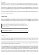
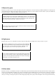
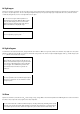

9 From red to green
Behind the door number 9, there is a 4.7 k
resistor (yellow, violet, red). It is intended as a series resistor for the green LED. As both LEDs are now at the input, the
output voltage defines the brightness ratio between the two colours. If the wire switch is closed, the red LED is on. Once the switch is opened, the red LED slowly
gets weaker and the green - brighter, until, finally, only the green LED is on.
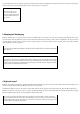
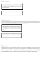
Info: The input current via the (+) input creates a voltage drop of about 10 mV at the resistance of 330
k
. With the switch closed, the voltage at the inverting input is zero Volts, i.e. the output voltage is
high. Once the switch is opened, the capacitor starts discharging. However, as it is placed between
output and inverting input, discharge is decelerated. Such circuit is also called an integrator. The
output voltage changes proportionally to charging current and time.
Mission: Modify the circuit so that instead of the switch, there is a touch-contact. This time, the finger
pressure must be stronger, because the resistance below 330 k
must be reached. It may be nec-
essary to slightly moisten the finger: 3 points.
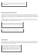
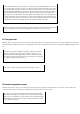
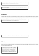
10 Light sensor
Behind the tenth door, there is a yellow LED. It is suited as a light sensor. Depending on the brightness, the circuit goes either red or green.
Info: Basically, every LED can be also used as a photosensor. Replace the LEDs and
check, which of the LEDs features higher sensitivity towards the given white light
source. Using a torch, you can also measure the distance, at which the output
toggles. The capacitor can be removed to speed up the measurement.
Mission: carry out the test without capacitor with different light sources. Search for
the areas, in which both LEDs at the input are glowing with roughly equal strength.
You can prove thereby that these lamps are flickering rapidly. A strongly flickering
lamp shows a wide range within which both LEDs are on. Find the most strongly
flickering lamp in your apartment and get: 4 points.
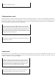
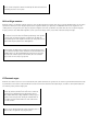
11 Colour mixer
Behind the eleventh door, you will find an electrolytic 22
µ
F (mikrofarad) capacitor. Note that the polarity must be always observed with an electrolytic capacitor.
The minus pole is labelled with a thick white line. The capacitor only insulates properly if installation direction is observed. If direction is wrong, the current flows
and the electrolytic capacitor can be gradually damaged. Here, the electrolytic capacitor is used to maintain a state, once set, for a long time. Using a self-made
switch, you can charge or discharge the capacitor. It enables changing output voltage of the op-amp and thus the brightness of the red and green LED. In this way,