
Data Sheet


3
Absolute Maximum Ratings Thermal Information
Supply Voltage
ICL7106, V+ to V- . . . . . . . . . . . . . . . . . . . . . . . . . . . . . . . . . . 15V
ICL7107, V+ to GND. . . . . . . . . . . . . . . . . . . . . . . . . . . . . . . . . 6V
ICL7107, V- to GND . . . . . . . . . . . . . . . . . . . . . . . . . . . . . . . . .-9V
Analog Input Voltage (Either Input) (Note 1). . . . . . . . . . . . . V+ to V-
Reference Input Voltage (Either Input) . . . . . . . . . . . . . . . . . V+ to V-
Clock Input
ICL7106 . . . . . . . . . . . . . . . . . . . . . . . . . . . . . . . . . . . TEST to V+
ICL7107 . . . . . . . . . . . . . . . . . . . . . . . . . . . . . . . . . . . .GND to V+
Operating Conditions
Temperature Range . . . . . . . . . . . . . . . . . . . . . . . . . . . .0
o
C to 70
o
C
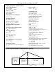
Thermal Resistance (Typical, Note 2) θ
JA
(
o
C/W)
PDIP Package . . . . . . . . . . . . . . . . . . . . . . . . . . . . . . . 50
MQFP Package . . . . . . . . . . . . . . . . . . . . . . . . . . . . . . 80
Maximum Junction Temperature . . . . . . . . . . . . . . . . . . . . . . . 150
o
C
Maximum Storage Temperature Range . . . . . . . . . .-65
o
C to 150
o
C
Maximum Lead Temperature (Soldering 10s) . . . . . . . . . . . . . 300
o
C
(MQFP - Lead Tips Only)
CAUTION: Stresses above those listed in “Absolute Maximum Ratings” may cause permanent damage to the device. This is a stress only rating and operation
of the device at these or any other conditions above those indicated in the operational sections of this specification is not implied.
NOTES:
1. Input voltages may exceed the supply voltages provided the input current is limited to ±100µA.
2. θ
JA
is measured with the component mounted on an evaluation PC board in free air.
Electrical Specifications (Note 3)
PARAMETER TEST CONDITIONS MIN TYP MAX UNIT
SYSTEM PERFORMANCE
Zero Input Reading V
IN
= 0.0V, Full Scale = 200mV -000.0 ±000.0 +000.0 Digital
Reading
Stability (Last Digit) (ICL7106S, ICL7107S
Only)
Fixed Input Voltage (Note 7) -000.0 ±000.0 +000.0 Digital
Reading
Ratiometric Reading V
lN
= V
REF
, V
REF
= 100mV 999 999/10
00
1000 Digital
Reading
Rollover Error -V
IN
= +V
lN
≅ 200mV
Difference in Reading for Equal Positive and
Negative Inputs Near Full Scale
- ±0.2 ±1 Counts
Linearity Full Scale = 200mV or Full Scale = 2V Maximum
Deviation from Best Straight Line Fit (Note 6)
- ±0.2 ±1 Counts
Common Mode Rejection Ratio V
CM
= 1V, V
IN
= 0V, Full Scale = 200mV (Note 6) - 50 - µV/V
Noise V
IN
= 0V, Full Scale = 200mV
(Peak-To-Peak Value Not Exceeded 95% of Time)
-15- µV
Leakage Current Input V
lN
= 0 (Note 6) - 1 10 pA
Zero Reading Drift V
lN
= 0, 0
o
C To 70
o
C (Note 6) - 0.2 1 µV/
o
C
Scale Factor Temperature Coefficient V
IN
= 199mV, 0
o
C To 70
o
C,
(Ext. Ref. 0ppm/
o
C) (Note 6)
- 1 5 ppm/
o
C
End Power Supply Character V+ Supply
Current
V
IN
= 0 (Does Not Include LED Current for ICL7107) - 1.0 1.8 mA
End Power Supply Character V- Supply Current ICL7107 Only - 0.6 1.8 mA
COMMON Pin Analog Common Voltage 25kΩ Between Common and
Positive Supply (With Respect to + Supply)
2.4 3.0 3.2 V
Temperature Coefficient of Analog Common 25kΩ Between Common and
Positive Supply (With Respect to + Supply)
- 80 - ppm/
o
C
DISPLAY DRIVER ICL7106 ONLY
Peak-To-Peak Segment Drive Voltage
Peak-To-Peak Backplane Drive Voltage
V+ = to V- = 9V (Note 5) 4 5.5 6 V
ICL7106, ICL7107, ICL7106S, ICL7107S