Data Sheet
Manuals
Brands
Conrad Components Manuals
Education & Development Kits
195731 Float switch Assembly kit 12 V DC
1
2
3
4
5
6
7
8
9
10
Table Of Contents
Table 1. Device summary
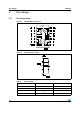
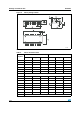
1 Pin settings
1.1 Pin connection
Figure 1. HCF4093B pin connection
Figure 2. Input equivalent circuit
Table 2. Pin description
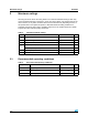
Table 3. Truth table
2 Maximum ratings
Table 4. Absolute maximum ratings
2.1 Recommended operating conditions
Table 5. Recommended operating conditions
3 Electrical characteristics
Table 6. DC specification
3.1 Dynamic electrical characteristics
Table 7. Dynamic electrical characteristics (Tamb = 25˚C, CL = 50 pF, RL = 200 KW, tr = tf = 20 ns)
Figure 3. Test circuit
Figure 4. Waveform: propagation delay times (f = 1 MHz; 50% duty cycle)
4 Package mechanical data
Figure 5. Plastic DIP-14 package outline
Table 8. Plastic DIP-14 mechanical data
Figure 6. SO-14 package outline
Table 9. SO-14 mechanical data
Figure 7. SO-14 tape and reel information
Table 10. SO-14 tape and reel information
5 Revision history
Table 11. Document revision history
HCF4093
Pin settings
3/13
T
able 3.
T
ruth table
Inputs
Outputs
A, C, E, G
B, D
, F
, H
J,
K, L, M
LL
H
LH
H
HLH
HH
L
1
2
3
4
5
...
...
13