
Technical Manual

SRT X-BAND RADAR SYSTEMS
ANNEX
304202P003 17 Rev. C
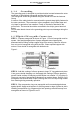
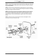
Figure 4:
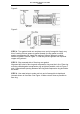
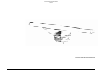
STEP 7 - Flatten tabs against flare ring. Use mallet as shown figure 5. Use only
enough force to flatten tabs. Do not strike tabs so hard as to reduce thickness of
metal. Trim any tab that protrudes past outside of groove in flare ring. After tabs
are flattened and trimmed, tabs should be cleaned with solvent to remove any
silicone grease. Face off connector body with contacts tabs should also be
cleaned thoroughly so that no grease is present in mating RF contact surfaces.
Clean inside of waveguide with bottle brush.
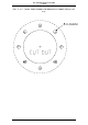
Figure 5:
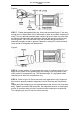
STEP 8 - Please smaller "O" ring gasket into groove in connector body. Do not
apply silicon grease to this gasket. Apply thin coating of silicon grease to rear
outer surface of compression ring. This will allow large "O" ring gasket inside
clamping nut to slide over compression ring.
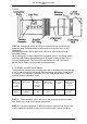
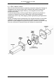
STEP 9 - Refer to figure 6. Place connector body against flare ring. Alignment
pins must be properly seated in alignment holes of flare ring and compression
ring.
Untape and slide clamping nut over assembled part and screw it onto connector
body. Tighten connection with wrenches. Use adjustable wrench on rectangular
portion of connector body to hold it in position while clamping nut is tightened.
Turn clamping nut only; Do not turn connector body.