
Technical Manual

SRT X-BAND RADAR SYSTEMS
ANNEX
304202P003 18 Rev. C
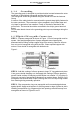
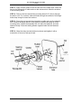
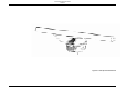
Figure 6:
STEP 10 - Waveguide should be check for leaks whenever connectors are
attached, when connector-attached waveguide is received at site, or after
installation.
At dependable method is to apply soap solution to cable connector and
pneumatic fittings.
When mating two UG type flanges with the gasket grooves, two flange gasket
must be used, if flange with gasket groove is mated to flange without groove,
use one flange gasket. Two mating EIA type flanges use only one flange
gasket. Do not apply silicone grease to flange gaskets.
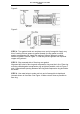
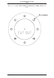
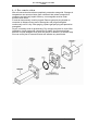
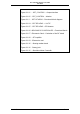
4.3 Wall/roof Feed-thru
These wall/roof feed-thru kits are designed to permit weatherproof path through
a roof or wall for elliptical waveguide. Each kit can be mounted to metal, wood
or concrete. A kit consists of a rubber boot, two metal flange halves, sealing
washers, and an adjustable clamp.
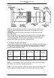
E
LLIPTICAL
W
AVEGUIDE
TYPE
NUMBER
K
IT NUMBER
ENTRANCE
HOLE
DIAMETER
IN. (MM)
B
OLT HOLE
CIRCLE IN
. (MM)
N
O. OF BOLT
HOLES
B
OOT FLANGE
DIAMETER
IN. (MM)
EW 85
35849A-3
3 (80)
4 (102)
8
5 (127)
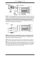
STEP 1 - Cut the entrance hole in the roof or wall to accommodate the cable
size. Refer to the chart for the proper dimension.
STEP 2 - Insert the waveguide or cable through the entrance hole and connect
it to the entrance hole and connect it to the components inside the building.