SRT X-BAND RADAR SYSTEMS ANNEX 4.1.6 Grounding The grounding point is designed to provide electrical contact between the outer conductor of the elliptical waveguide and the ship’s ground. The waveguide should be grounded along the vertical run near the Antenna Group. A section of the cable jacket is removed and the ground strap tightly fastened to the outer conductor. The connection is then wrapped in butyl rubber tape and vinyl tape for protection from weather.
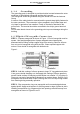
SRT X-BAND RADAR SYSTEMS ANNEX Figure 2: Figure 3: STEP 4 - Turn gasket inside out and place over end of waveguide. Apply very thin of coating silicone grease to gasket threads, the flip gasket over and against compression ring. Apply thin coating of silicone grease to outside surface of gasket. Refer to Figure 3. Clean any silicone grease from exposed copper using solvent. STEP 5 - Slip recessed side of flare ring over gasket. Alignment pin holes in flare ring and compression ring must be in line.
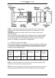
SRT X-BAND RADAR SYSTEMS ANNEX Figure 4: STEP 7 - Flatten tabs against flare ring. Use mallet as shown figure 5. Use only enough force to flatten tabs. Do not strike tabs so hard as to reduce thickness of metal. Trim any tab that protrudes past outside of groove in flare ring. After tabs are flattened and trimmed, tabs should be cleaned with solvent to remove any silicone grease.
SRT X-BAND RADAR SYSTEMS ANNEX Figure 6: STEP 10 - Waveguide should be check for leaks whenever connectors are attached, when connector-attached waveguide is received at site, or after installation. At dependable method is to apply soap solution to cable connector and pneumatic fittings. When mating two UG type flanges with the gasket grooves, two flange gasket must be used, if flange with gasket groove is mated to flange without groove, use one flange gasket.
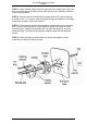
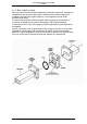
SRT X-BAND RADAR SYSTEMS ANNEX STEP 3 - Apply silicone grease to the hole and slit of the rubber boot. Place the boot on the waveguide or cable and over the entrance hole. Mark the locations of the mounting holes. STEP 4 - Remove the boot and drill the mounting holes 5/16" (8 mm) through the wall or roof. For concrete, either drill holes through the material or drill larger holes deep enough to insert bolt anchors. STEP 5 - Place the boot around the waveguide or cable and over the entrance hole.
SRT X-BAND RADAR SYSTEMS ANNEX FIG. 5.3.2 - WALL FEED THROUGH DRILLING TEMPLATE (Scale 1:1): 304202P003 20 Rev.
SRT X-BAND RADAR SYSTEMS ANNEX 4.4 Pressurisation After all connections have been completed, pressurise waveguide. Changes in temperature can cause moisture from outside air that enters waveguide to condense and seriously impair efficiency, so waveguide must be under pressure at all times. If moist air has entered, must be purged. Remove gas port plug located on connector at Antenna Group end of waveguide, and purge waveguide continuously until it is dry.
SRT X-BAND RADAR SYSTEMS FIGURES CHAPTER 9 FIGURES The following figures and drawings are included after this pages: Figure 9.1.1 - SRT 12 KW - General View Figure 9.1.2 - SRT 12 KW – External view Figure 9.1.3 - Pedestal External View Figure 9.1.4 - Pedestal Internal View Figure 9.1.5 - Motoreducer assy Figure 9.1.6 - Electronics Rack Figure 9.1.7 - SRT Functional Block Diagram for 6’ Antenna Figure 9.1.8 - SRT Internal Connection Figure 9.1.9 - SRT Internal voltage and signals Figure 9.1.
SRT X-BAND RADAR SYSTEMS FIGURES Figure 9.1.21 - SRT_CONTROL – Output interface Figure 9.1.22 - SRT_CONTROL – Monitor Figure 9.1.3 - SRT RF HEAD – Functional block diagram Figure 9.1.24 - SRT RF HEAD – L.N.F.E. Figure 9.1.25 - SRT RF HEAD – RF Detector Figure 9.1.26 - BRUSHLESS CONTROLLER – Functional blocks Figure 9.1.27 - Electronics Rack – Particular of the RF Head Figure 9.1.28 - RF Amplifier Figure 9.1.29 - Electronics rack Figure 9.1.30 - Bearing reader board Figure 9.1.31 - Rotary joint Figure 9.1.
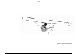
SRT X-BAND RADAR SYSTEMS FIGURES Figure 9.1.1 SRT Up mast General View 304202P003 9.3 Rev.
SRT X-BAND RADAR SYSTEMS FIGURES Figure 9.1.2 SRT Up mast– External view 304202P003 9.4 Rev.
SRT X-BAND RADAR SYSTEMS FIGURES 1 2 3 4 Figure 9.1.3 Pedestal External View 304202P003 9.5 Rev.
SRT X-BAND RADAR SYSTEMS FIGURES 7 9 4 2 6 1 10 5 1 3 8 Figure 9.1.4 Pedestal Internal View 304202P003 9.6 Rev.
SRT X-BAND RADAR SYSTEMS FIGURES 3 2 4 1 Figure 9.1.5 Motoreducer assy 304202P003 9.7 Rev.
SRT X-BAND RADAR SYSTEMS FIGURES 8 6 8 6 4 1 2 3 7 9 7 Figure 9.1.6 Electronics Rack 304202P003 9.8 Rev.
SRT X-BAND RADAR SYSTEMS FIGURES Speed Control Main Power Brushless Motor Controls Bearing Reader SRT_Control SRT_Power RF Head SRT_Mos Figure 9.1.7 SRT Functional Block Diagram for 6’ Antenna 304202P003 9.9 Rev.
SRT X-BAND RADAR SYSTEMS FIGURES Figure 9.1.8 SRT Internal Connection 304202P003 9.10 Rev.
SRT X-BAND RADAR SYSTEMS FIGURES PWON Start LINE Vel 12 VT -15V +15V -5V +150V +24V STC +5V SRT_Power Speed Control SRT_Control HVON SPA MPA LPA SB1 SB2 +5V HV OK Video HV STOP Tune RF Amplifier SW Fil Fil ON V Fil M.PC TR Pull TR Push 15 Iso -5V + 15 V + 700 V V Fil HV Stop SRT_Mos Figure 9.1.9 SRT Internal voltage and signals 304202P003 9.11 Rev.
SRT X-BAND RADAR SYSTEMS FIGURES 3 1 2 5 4 Figure 9.1.10 304202P003 9.12 SRT_POWER - Board Rev.
SRT X-BAND RADAR SYSTEMS FIGURES 50 Vdc Input Protection L.V.P.S. H.V.P.S. R8 DL1 GND 304202P003 9.13 Rev.
SRT X-BAND RADAR SYSTEMS FIGURES 50 Vdc Wrong polarity protection Over Current protection Voltage sensor 12 VT To SRT_Control Line To SRT_Control DL1 LVPS HVPS Figure 9.1.12 304202P003 9.14 SRT_POWER – Protection circuits Rev.
SRT X-BAND RADAR SYSTEMS FIGURES F2 16 IVac 5 Vac Filter Transformer 50 Vdc Filters & Regulators 16 Vac F7 +15 Iso To SRT_MOS -15VF -5V 16 Vac 24 Vac F5 +24V F6 +15VF F4 +5V General power supply F3 MOSFET MOSFET FLYBACK CONTROLLER V FIL To SRT_MOS and SRT_Control PW ON DL2 VFIL CONTROLLER SW Fil From SRT_Control Fil ON Figure 9.1.13 304202P003 9.15 SRT_POWER – LVPS circuits Rev.
SRT X-BAND RADAR SYSTEMS FIGURES + 700 V Filters & Regulators 700 Vac 50 Vdc Filter To SRT_MOS Transformer 460 Vac 230 Vac + 150 V DL3 MOSFET Feedback and Controls To SRT_Control HV Stop From SRT_MOS HV OK FLYBACK CONTROLLER HV ON LPA From / To SRT_Control MPA SPA Figure 9.1.14 304202P003 9.16 SRT_POWER – HVPS circuits Rev.
SRT X-BAND RADAR SYSTEMS FIGURES Figure 9.1.15 304202P003 9.17 SRT_MOS – Board Rev.
SRT X-BAND RADAR SYSTEMS FIGURES + 700 V + 15 Iso Pulse Transformer From SRT_Power + 15 V TR Push Driver Isolation Transformer Driver Mosfet Current Transformer Fil ( Green ) K ( Yellow ) To Magnetron Magnetron Gnd From SRT_Control TR Pull Driver Mosfet Magnetron Current -5V From / to SRT_Power To SRT_Control 15 Iso Sensor + 15 V V Fil HV Stop Figure 9.1.16 304202P003 9.18 SRT_MOS – Block diagram Rev.
SRT X-BAND RADAR SYSTEMS FIGURES 3 6 4 7 2 1 Figure 9.1.17 5 304202P003 9.19 SRT_CONTROL Board Rev.
SRT X-BAND RADAR SYSTEMS FIGURES Monitor ( Performance and Voltage ) Microprocessor Output Interface Input Interface Gate Array Figure 9.1.18 304202P003 9.20 SRT_CONTROL – Blocks Rev.
SRT X-BAND RADAR SYSTEMS FIGURES Figure 9.1.19 304202P003 9.21 SRT_CONTROL – Microprocessor and Gate Array Rev.
SRT X-BAND RADAR SYSTEMS FIGURES Figure 9.1.20 304202P003 9.22 SRT_CONTROL – Input interface Rev.
SRT X-BAND RADAR SYSTEMS FIGURES Figure 9.1.21 304202P003 9.23 SRT_CONTROL – Output interface Rev.
SRT X-BAND RADAR SYSTEMS FIGURES Figure 9.1.22 304202P003 9.24 SRT_CONTROL – Monitor Rev.
SRT X-BAND RADAR SYSTEMS FIGURES TO - FROM ANTENNA RF and ECHO Pulse Magnetron Pulse K Circulator Limiter RF Amplifier Low Noise Front End Pulse FIL Tune +5V 60MHz A ECHO RF From SRT_MOS Video RF Detector Tune +5V From / To SRT_Control SB1 SB2 STC V Tune Figure 9.1.23 304202P003 9.25 SRT RF HEAD – Functional block diagram Rev.
SRT X-BAND RADAR SYSTEMS FIGURES Tune Voltage Balanced Mixer WG-Mic Transition RF in 0° LNA 0° 90° Isolator Divider Balanced Mixer 0° ~ 60 MHz IF Out 0° From / To RF Detector 90° Moni CKT Monitor Out + 5 Vdc Figure 9.1.24 304202P003 9.26 SRT RF HEAD – L.N.F.E. Rev.
SRT X-BAND RADAR SYSTEMS FIGURES Logaritinc Amplifier BP Filter RF in 20 dB 50 dB Variable Attenuator 32 dB Tune Out Buffer Band selector Logaritinc Amplifier Video Out Buffer From / To SRT_Control - 12V + 12V From / To RF Detector SWB1 STC Filters DC/DC Converter Level translator + 5 Vdc Tune Voltage Monitor Figure 9.1.25 304202P003 9.27 SRT RF HEAD – RF Detector Rev.
SRT X-BAND RADAR SYSTEMS FIGURES Main Power Green Led LM 7812 R Controls MC 33035 Brushless Controller 3 X IR 2103 Half Bridge Driver 6 Power Mosfet Brushless Motor S T Current Sensor Red Led Closed Loop Brushless Motor Adapter MC 33039 Figure 9.1.26 304202P003 9.28 BRUSHLESS CONTROLLER – Functional blocks Rev.
SRT X-BAND RADAR SYSTEMS FIGURES Figure 9.1.27 304202P003 9.29 Electronics Rack – Particular of the RF Head Rev.
SRT X-BAND RADAR SYSTEMS FIGURES 2 1 Figure 9.1.28 304202P003 9.30 RF Amplifier Rev.
SRT X-BAND RADAR SYSTEMS FIGURES 1 Figure 9.1.29 304202P003 9.31 Electronics rack Rev.
SRT X-BAND RADAR SYSTEMS FIGURES 1 2 Figure 9.1.30 304202P003 9.32 Bearing reader board Rev.
SRT X-BAND RADAR SYSTEMS FIGURES 1 Figure 9.1.31 304202P003 9.33 Rotary joint Rev.
SRT X-BAND RADAR SYSTEMS FIGURES 1 2 Figure 9.1.32 304202P003 9.34 Brushless Motor Controller Rev.
SRT X-BAND RADAR SYSTEMS FIGURES Figure 9.1.33 304202P003 9.35 SRT Downmast Pedestal dimensions drawing Rev.
SRT X-BAND RADAR SYSTEMS FIGURES 1 2 Figure 9.1.34 SRT Downmast Configuration Mechanical Assembly 304202P003 9.36 Rev.
SRT X-BAND RADAR SYSTEMS FIGURES 1 2 3 Figure 9.1.35 SRT Downmast Configuration Mechanical Assembly 304202P003 9.37 Rev.
SRT X-BAND RADAR SYSTEMS FIGURES Figure 9.1.36 SRT Adapter Box 304202P003 9.38 Rev.